Pages

Solenoid valve controller with MCU

Introduction of Printer Port and MCU controller for Solenoid Valve

In this project our task was to develop a complete circuit to control solenoid using PC interface. Computer system is interfaced with microcontroller with the help of parallel port. This project is to develop a complete system to control Solenoid Valve System. The main part of this project is the interfacing of microcontroller to the PC and with the other devices. The data is provided by the pc to the microcontroller and this data is the provided to the DAC which generates different voltages levels according to the input given this data is the provided to the OPAM which provides us the required voltage levels. This project is divided in to four parts or stages. Which are as under: 

  • PC and Parallel Port Interfacing 
  • Designing Circuit and selection of components or Devices 
  • Microcontroller Programming or Coding 
  • Solenoid valves controlling testing 

Overview of the Project

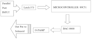
Before giving the detail description of each equipment used, it is important to describe the general overview over the project circuitry, that is how the data starts from PC and being received by solenoid in the end. First of all the data from PC is send to LATCH 373 using parallel port of PC. The data is received on LATCH on pins D1, D2, D3, D4, D5, D6, D7, D8 from parallel port pins 2,3,4,5,6,7,8,9 respectively. Pin 10 is grounded and pin 20 is been given VCC 20 volts. The is transferred to micro controller on port-I on pins 1-8. The corresponding pins of latch are Q1, Q2, Q3, Q4, Q5, Q6, Q7, and Q8 respectively. The data is then transmitted To port 2 on pins 21 to 28. The next step is to send data on DAC-0800. The data from micro controller pin 2 is then received by DAC on pins 12 to 5 respectively. Then data is received by op-amp on pins 2 and 3 from DAC pins 3 and 4 respectively. Finally, the data received by op-amp is connected to solenoid, which has different variations as requirements of user. This was a brief summary of the data from PC till the last object solenoid. The diagram of above procedure is given below. 
Solenoid Valve Control
Block Diagram of Printer Port Interface to MCU to Control Solenoid

PC Parallel Port Interfacing 

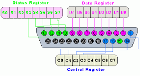
Parallel port of computer is the one of oldest port available with PC to interface devices with computer through it. The interface through printer port is easy for developing computer-controlled system and projects. This feature of parallel port makes programming of parallel port convenient in electronics hobbyist world. The parallel or printer port is very often used in robots, test equipment, microcontroller programmers, home automation, etc. The primary use of parallel port was to connect printers with computer as it was designed for this purpose, thus, it is usually also called Printer Port. The parallel port connector can be searched at the rear side panel of PC. It is a 25-pin female DB25 connector to which normally printer was connected. The PCs have only one parallel port normally. Additional Parallel Ports can be added inserting ISA/PCI cards. 
Parallel or Printer Port
DB25 PIN Connection of Printer Port


We will use parallel port here to connect it to the microcontroller through the latches. The data from PC will be latched and then forwarded to the microcontroller. A simplified diagram of a parallel port along with its pin configuration is given blow. The pin outs of connector is shown in the picture below. Parallel Port Pins The data input and output lines in DB25 connector of parallel port can be divided in to three sub-groups, which are listed as below: 

  1. Data lines (data bus) 
  2. Control lines 
  3. Status lines 

The brief introduction of these groups is as, the data is transferred over data I/O lines, Control lines are used to control the peripheral. The peripheral can return some status signals back to computer, for this purpose the Status lines are used. These I/O lines are connected to Data, Control and Status registers internally inside PC. 

Latch 373 Description 

Latch LMS-373 is 20 pin IC. Which is used here to transfer the data from PC to controller. It received the data on clock pulses. When the enable (pin 11) is taken low the output will be latched at the level of the data that was set up. The eight flip-flops of the 74LS373 are edge-triggered D-type flip flops. When there is the positive transition of the clock, the Q outputs of flipflop/ latch will be set to the logic level which was at D inputs at that time.. The output control of latch does not affect the internal operation of the latches . That is, the old data on the latch can be retained or new data can be entered to it even when the outputs are switched off. 

ATMEL89C51 Description 

The AT89C51 is a low power, high performance 8-bit micro controller with 4K bytes of programmable and erasable read only memory (PEPROM). The device is manufactured using ATMEL’s high density nonvolatile memory technology and comparable with the industry of MCS-51TM instruction set and pinout. The on chip flash can be reprogrammed by first erasing the last program using ultra violet rays and then write new program on it using software. 

OJ0800 DAC

A digital to analog converter (DAC) is an integrated circuit that converts a digital signal input to an analog output voltage or current that is the binary weighted equivalent of the digital input code. Modern DAC s are, effectively, an array of matched current sources optimized for frequency domain performance .To handle both strong and week signals DACS require large dynamic range. Beside these there are a number of the DC parameters such as integral nonlinearities (INL) and differential nonlinearities (DNL), that are considered important because of their influence on SFDR parameters .The resolution of the DAC is dependent upon the type of the DAC, whether it is 16 bit or 8 bit, higher the number of bits smaller will be the quantization error. In our project we have used CJ0800, which is an 8 bits DAC .So the number of quantization levels are equal to 256 levels. The ratio of the input voltage range to the number of quantization levels will determine the output voltage, but remember that larger the input voltage range greater will be the quantization error. Several factors influence the selection of the DACs 

  • DAC resolution 
  • DAC dynamic specifications 
  • Operating frequencies 
  • Type of the signal 
  • Supply voltages 
  • Cost 

DACs error will add to the error caused by the resolution of the converter. A given DAC may or may not include the dc or ac error specifications. Offset error is critical in dc applications. For this reason, a buffer OP AMP must be selected that does not contribute to the problem its own offset voltages should be much less than that of the converter. The settling time of the DAC is time between the switching of the digital inputs of the converter and the time when Its output reaches its final value and remains within a specified error band or the tolerance band. It is the reciprocal of the maximum D/A conversion rate. 

LM741 Operational Amplifier General Description 

An operational amplifier is an integrated circuit that produces an output voltage that is An amplified replica of the difference between the two input voltages. An op amp can be characterized by following transfer function. where is the open loop gain of the operational amplifier . Most op amps are of monolithic type and there are dozens of different manufacturers. Op Amps are used in conjunction with other circuit components such as resisters and capacitors to perform various mathematical operations as well as a multitude of tasks. Two types of inputs are available on the integrated IC such as LM741 which we used in our project. These are named as inverting and non-inverting inputs. The op amp is ideally completely insensitive to the voltage components, which are common to the inputs. The open loop gain is a positive dimensionless constant and is usually very large, often in the range of hundreds of thousands at very low frequencies (0-30) Hz. Op Amps enter the saturation region when operated in the open loop so that a closed loop operation is always recommended, as open loop operations causes severe distortion of the signal. In the feed back configurations the gain of the amplifier is only dependent on the external components (capacitors and resistors) in our project we used the op amp as a non-inverting amplifier in order to get the positive output voltage required for the solenoid operation. The gain of a non-inverting amplifier is calculated using gain equation. Under these conditions op amp is operating as a closed loop system and the fraction of the output voltage is feed back to the inverting input terminal and is called the feed back factor. 

CHARACTERISTICS OF AN IDEAL OP AMP 

The ideal characteristics of ideal op amp are given as follow; • Infinite impedance • Zero output impedance • Infinite open loop gain The op amp diverges from the ideal characteristics due to many reasons. There are even more severe problems with op amps namely CMRR and input and offset voltages nulls. 

INPUT OFFSET VOLTAGES 

 All op amps require a small voltage between their inverting and no inverting inputs to balance the mismatches due to unavoidable process variations. The require voltage is known as input offset voltage and is normally modeled as no inverting input deriving source. The input offset voltage is of concern anytime when dc accuracy is required for the circuit. The method to null the offset voltages is to use external components to null the inputs on a single op amp chip. A potentiometer is connected between the null inputs with adjustable terminal connected to the negative supply through the series of the resisters, the input offset voltages can be nullified by shorting the inputs and adjusting the potentiometer until output voltage is zero. 

Solenoid Valve 

Solenoid is defined as a device used to control the motion of an iron bar according to the voltage applied to it. A coil of insulated wire is the main component of solenoid in which a magnetic field is produced with the flow of electric current through the coil. A coil which is surrounding a movable iron core which is pulled when the coil is electrically energized. This movement can be used to perform some specific mechanical work, such as opening a mechanical process valve, or operate an electrical switch. Cylindrical coil having larger length as compared to diameter of coil. When the current is passed through the coil of the solenoid, it comes a magnet until the current is there. The magnetic field is established due to passing current from the coil of solenoid. Therefore, it can be said that the solenoids are electromagnetic switches. When electricity passes through the solenoid, the magnetic field formed which forces to move a metal piston. The piston of solenoid is usually connected or attached to a mechanical mechanism that performs the desired specific function. The movement of metal piston causes actually to execute the application work. The application work is like operation of a mechanical valve, operation of a switch, or mechanical linkage process. In engineering fields, the solenoid is a electro-mechanical device that converts electrical energy into some where linear motion of a part. The Solenoids are usually developed or constructed to use electricity for control of compressed air, or pressurized fluids i.e. the hydraulic solenoids. The Solenoid valves are operated with electric power supply and used in variety of industrial application where the fluids are required to control automatically. Parallel to the technologic development its fields of usage have been increasing. The Solenoid valves have been derived from the principal that a magnetic field, forced by the electric energy with the help of a coil, moves some mechanical parts. Depending upon the use of project or system or application, the Solenoid valves can be developed with 02 or more ways and in different sizes as per needs. The electric supply to solenoid can be 6, 12, 24, 48, 72, 110, 220 VAC or VDC according to application or system or project usage. In Solenoid Valves the widely used body material is brass, but stainless steel, bronze, cast iron, steel or plastic body valves can be produced as well. According to the working principle of the Solenoid Valves, these can be classified into two main classes as Direct Acting Solenoid and pilot operated Solenoid. The Solenoid valves can also be classified in accordance to the fluid types control by these. The Solenoid Valves are also designed as ON or OFF type valves subject to availability of electricity. Thus, the solenoid valves can be the valve which are Normally Open or Normally Closed. Whenever we are concerned with the design of the solenoid then the major concerns are of these two areas. Determining the number of turns and the design related to electrical parameters and Design related to the mechanical parameters.

Software for Parallel Port Interface


/* Include the right header file, the library files*/
#include<iostream.h> 
#include<conio.h>
/* main program starts here*/
void main(void)
{
clrscr(); // Clear the screen of computer
int data=0x378; \\ initializing the parallel port
int n;	\\ Declaring variables
char ch; // declaration of a temporary variable
do{	\\ multiple input loop
cout<<"\t\tInput any hex value to be transfered\n";
cin>>hex>>n;
cout<<"The Data is  ";
cout<<hex<<n<<endl;
outportb(data,n); \\ sending data on port
cout<<"\t\t\tPress any key to continue\n";
cout<<"\t\t\tPress e twice to exit\n";
ch=getche(); // get a character from keyboard
clrscr();
}
while(ch!='e');	\\ program exit condition check
getch();
}
How to connect solenoid valve to microcontroller? What is a solenoid controller? Which microcontroller is best suitable to drive 4 solenoid What are the three 3 components of solenoid? Arduino Uno Micro controller c. Solenoid valve What is solenoid valve in mechatronics? Adafruit Mini Push‑pull Solenoid uxcell a14092600... Open Fram... Adafruit Lock‑style Solenoid Adafruit 412 Push‑Pull Solenoid solenoid valve arduino code solenoid valve arduino relay code solenoid valve control using microcontroller 12v solenoid valve arduino proportional solenoid valve + arduino control 24v solenoid with arduino 5v solenoid arduino arduino solenoid water valve solenoid valve arduino Plc Industrial Control Board Mcu Control Panel solenoid valve arduino code How to wire 12V Solenoid Valve - 3/4'' to Node MCU solenoid valve arduino relay code Nodemcu-esp8266 Wifi controlled motor, solenoid, valve, 5v solenoid valve arduino MCP23017 16-Channel 8W 12V FET Solenoid Driver 12v solenoid valve arduino How to control a Solenoid Valve with Arduino control 24v solenoid with arduino Solenoid Valve Interfacing With Arduino arduino solenoid driver arduino solenoid water valve control 24v solenoid with arduino solenoid valve arduino relay code control 12v solenoid valve with arduino 5v solenoid arduino solenoid valve control using microcontroller arduino solenoid relay solenoid valve arduino code arduino solenoid driver, Switching multiple solenoid valves with microcontroller, solenoid working principle, Isolating the solenoid and driving relay power supply
How to avoid voltage spikes from solenoid valves?, Battery-powered 3-5 V MCU, but 12 V solenoids 
application of solenoid actuator, What all do I need to control a 12V solenoid valve , application of solenoid valve, What should I use to drive a solenoid that requires 12, What is an industrial solenoid?, Which industry used solenoid valve?, What are the applications of solenoid in automotive?, How are solenoids useful?, what are solenoids used for in cars, uses of solenoid in daily life, 4 applications of solenoid, what is solenoid, solenoid engine project

DESIGNING AUTOMATIC GATES USING MICROCONTROLLERS FOR PARKING

Aim and Objective of Microcontroller based Automation Project:

 The main Aims and Objectives of this project is to design and develop an automatic car parking system having fully automatic gates. The use of automatic gates for various purposes can be seen in many application in different industries as well as in security systems and also at tool plazas. Same is here, we will implement this idea in our automatic car parking system. Introduction of Project: The application of the automatic control systems in different system can be observed rapidly grown during the past few decades. Same as the automatic barrier control system. The manual working or handling of any application has less accuracy as compare to the automated microcontroller based control systems. The project is basically giving an initial theme that how we can approach to an automatic barrier control system using 8051 microcontrollers. “Two gates or doors located at the entrance and exit of car parking will be opened and closed through the use of two stepper motors which be governed by Microcontroller at back of the whole system. Some of the application of automatic door controls are airports, toll gates, railway crossings etc.

 Overview of the Automatic Car Parking System: 

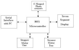
The parking system is based around an At89C51 micro-controller and U-shaped photo sensors. It is quick and efficient in operation. The microcontroller is serially interfaced to the PC using serial port and the RS-232 Transmitter/Receiver. The components like u-shaped Photo sensors, stepper motor and At89C51 microcontroller will be configured to each to have the control of the entire operation of the car parking control system collectively. The seven segment display units along with the serial interface will be responsible to display the number of cars already parked in the parking lot. Block diagram of the system is shown in figure 1 below. 

Automated Car Parking System
Block Diagram of The Automated Car Parking System

Basic Components Required for development of Automatic Parking System:

 In the context of design and implementation of car parking control system required the use of following the important components: 

  • Stepper Motor 
  • U-shaped Photo Sensors 
  • Seven segment Display 
  • Serial Interfacing 

The components used in this automation project will be discussed here briefly one by one. 

Stepper Motor

A stepper motor is a digital electrical device used in various electronics application for controlled and precise motion of various rotary devices. The step motor moves under the commands of digital instructions accurately, through a specific electronics control circuit. This is the unique functionality of a step motor. In brief, the step motors are electrical motors which are driven through the digital pulses in contrast to other motors where continuously voltage are applied to have motion. The pulse give to stepper motor is equal one step. The Two stepper motors are used in this project. One is for incoming gate and other is for outgoing gate. To step a motor in a particular direction a specific switching sequences need to be followed. There are two configurations of electric connections with stepper motor: 6-wire configuration and the second is 8-wire configuration. 

U-shaped Photo Sensors

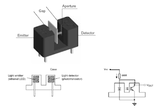
The u-shaped photo sensor is a device has two main electronics components inside it which are emitting-light sources and the detectors. The LED and photo transistor or photo diode are mounted face-to-in the sensor. The collector of the phototransistor acts as an output pin, connected to microcontroller pins. If an object comes between the gap between the LED & photo transistor the light will be blocked. The logic level will be changed on the output of the sensor, indication the interruption. This condition generates required signal which will be read by microcontroller. 

Optocoupler U type sensor
U-shaped input Optocoupler sensor

Seven segment Display

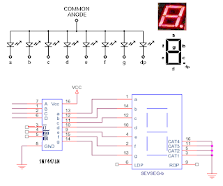
The LED seven-segment display is used in many electronic devices to display useful information to the user of that device. The construction of the seven segments display is very simple as the 7 LEDs are combined into one casing to make a device for the displaying numbers from 0 to 9. The one wire of all the seven LED are kept common. Therefore, these are constructed in two ways, the common anode type or common cathode type. In common anode type display unit, the positive leg of each LED is made internally common and tied to Vcc, whereas the other negative legs are open for external interface. The assembly is reversed for common cathode type units. 

7 segment display
Common anode configuration Seven segment display

Serial Interfacing

The micro-controller is interfaced to the PC by serial port through ICL232 logic level converter. The personal computer and AT89C51 microcontroller are interfaced through RS-232 for serial communication. RS-232 Serial Communication The RS-232 is a serial communication standard which enables data to be transferred in serial form between two devices. The data is transmitted in serial bit stream from one device to another. The parameters specify an RS-232 link between two devices are usually the baud rate, data width, parity and stop bits and are described below. 

  • Baud rate: The baud rate is defined as the number of bits per second. The baud rate determines the quantity of information communicated in a unit time. It may in some where in range of 110 and 76800 bits per second. 
  • Data width: The data width of a byte can be either 8 bits or 7. 
  • Parity: The parity bit in serial communication is used to check the correctness of the transmitted or received data. Parity bit can be zero or one corresponds to even, odd.
  • Stop bits: The stop bit in serial communication is used as the terminator bit.

Serial data is transmitted and received in frames where a frame consists of: 1 start bit, 7 or 8 data bits, Optional parity bit, 1 stop bit. In many applications 10 bits are used to specify an RS-232 frame, consisting of 1 start bit, 8 data bits, no parity bit, and 1 stop bit. For Example, character ‘A’ has an ASCII bit pattern ‘01000001’ and is transmitted. Two types of connectors are used for RS232 communication. These are 25-way (known as DB25) and the 9-pin D-type connector (also known as DB9). 

  • SG: signal ground. This pin is used in all RS-232 cables for ground connection. 
  • RD: Received data. Data is received at this pin. This pin is used in all two-way communication.
  • TD: Transmit data. Data is sent out from this pin. This pin is used in all two-way communication. 
  • RTS: Request to send. This signal is asserted when the device requests data to be send. 
  • CTS: Clear to send. This signal is stated when the device is ready to accept data serially. 
  • DTR: data terminal ready. This signal is asserted to indicate the device is ready. 
  • DSR: Data set ready. This signal indicates, by the device at another end, that is ready. 
  • CD: Carrier detect. This CD shows that a carrier signal has been detected by a modem or device which is connected to the line. 

RS232 Signals Levels A voltage of +3 to+12 indicates an on state, while a voltage of -3 to -12 indicates an off stage. Standard TTL logic devices, including 89c51 microcontroller. Operate with TTL logic levels between the voltages of 0 and +5V. The Voltage level converter ICs convert the voltage levels between the TTL level and RS232 voltage levels. E.g. ICL-232, MAX-232 etc. 

The Hardware Description and Construction of electronics circuit boards

The whole system is consisting of some small electronics board separately developed to make clear understandings of working of system.

Stepper Motor Control Board 

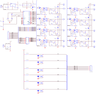
The electronics circuit board to drive stepper motor is designed to handle up to four stepper motors. But the requirement of this project is only the two. Remaining the slot of two stepper motors can be used for the further modification in project. The port 0 of microcontroller is used to drive the above said two motors. The P0.0 to P0.3 drive one motor while P0.4 to P0.7 for second stepper motor. A TTL latch IC is used to latch the logic level of these port pins. The P3.5 is connected to enable of the latch. Figure below shows the complete circuit diagram of stepper motor driver board. An optocoupler is used to have electrical isolation between the motor controller board and the rest of electronics. The microcontroller AT89S51 actually determines the needs and then send the control signal to the stepper motor controller board for appropriate rotation of stepper motor with energizing coil of the stepper motor so that each step of it covers about 1.8 degree of rotation. The current of each motor coil is about 1Amp. There is a diode is used in parallel to the coil of stepper motor to prevent the damage of transistors with high back current due to change in emf of the coil. These diodes setup like this are often known as freewheeling diodes. 

Sensors Board:

This hardware unit or board has six photo sensors. The output pin of every sensor is connected to one pin of the controller. As shown in figure 08 sensors generate a high pulse as beam is cut by ant small object. Three sensors used to operate one motor. Port1 is dedicated to the sensors as shown in figure below. By cutting beam of sensor S1 Motor start rotating in clockwise direction, then cutting the beam of sensor S2 motor stops for some time then start rotating in counter clock wise direction. At the end-cutting beam of S3 motor stops. The second stepper motor will operate the sensors S4, S5 and S6 when operated as discussed earlier. 

Steper Motor Driver
Stepper Motor Controller and Opto Coupler input Board

Seven Segment Display Board:

 This hardware is used to display the number of cars in the parking lot. The display board has six-segment display units or digits on it. The segment driver IC named SN7447AN which is a TTL IC is used to drive the seven-segment digit along with a three to eight-line decoder to select the corresponding digit. The figure below shows the circuit diagram of the seven-segment board. The Port2 of the Microcontroller is use to operate the display board for appropriate digit display on the respective unit. Serial Interfacing Board The PC placed in the control room for the help of operator will display the useful information about the parking capacity of car parking space in real time. The Microcontroller have input data from sensor and have the basic information of parking which will be transmitted to PC through the use of serial communication as discussed earlier. The circuit diagram of the serial communication board is show along with the display board in figure below.

LED Seven Segment Display Driver and RS-232 serial communication Board

Software description of the project

As we have discussed the hardware of this project has four peripherals section interfaced with the microcontroller. Therefore, the whole software program written for this project for microcontroller At89s51 is consisting of four main routines to make system functional, the subroutines of the program are listed below: 

  • Stepper motor subroutine 
  • Optical Sensor subroutine 
  • Seven segment subroutine 
  • Serial interrupt subroutine 

Stepper Motor Subroutine 

The Port0 of the microcontroller is used for controlling the stepping sequence of stepper motors at the entry and exit gates of car parking system. The Lower Nibble of Port0 of MCU is used for controlling the stepper motor number 01 which is mounted and placed at the entry gate. The Upper Nibble of Port0 is used to control the stepper motor number 02 which is mounted and place at the exit gate. The bits of port0 of MCU are set and reset according to the stepping sequence of each motor as listed in program. There are total six control bits in this sub-routine in which the two control bits are used to select and initiate the operation of stepper motors at the entry or exit gate. The three control bits of the stepper motor has specific function, one bit is used to initiate or select the motor and remaining two bits are used to control the motion. It may be noted that the operation of stepper motors is directly related to the input from sensor which is interpreted in the MCU and execution is accordingly done by passing appropriate commands to motors. 

Optical Sensor Subroutine

Optical sensors are connected to the port1 of the microcontroller. These input signal from these sensors are bases for the suitable initiation to the stepper motor subroutine. Each sensor is installed at a special location for performing a desire task such as to detect a entering vehicle or leaving the parking space, to detect gate current position whether it is fully opened o fully closed or in between the opening and closing position through the implementation of limit switches. The system remains in waiting condition until one of the sensor is triggered by arrival of a car or leaving of any vehicle. The sensors are placed at the entry and exit points of parking area gates to detects the vehicles passing through each gate. The two sensors are used to detect opening limit of each gate and other two to detect closing limit of each gate. When an entry gate sensor give signal then the seven-segment display subroutine is called along with the serial interrupt subroutine. The display unit will update the current number of cars present in the parking area. The count will be incremented correspondingly with entry gate control bit set and reset sequence. When an exit gate sensor is triggered the corresponding control bit will be set and the seven-segment display subroutine will also be called along with the serial interrupt subroutine. This will update the current number of cars present in the parking area and will be display accordingly on local display unit as well as in the computer screen placed in control room for the use of operator. Similarly, the count will decrement in response of the exit gate control bit set and reset sequence. The open limit gate sensors turn the motor in reverse direction after a delay and the close limit gate sensor turns the motor off for entry and exit gate. 

Seven Segment Subroutine 

The Port2 of At89s51 is used for the interfacing of the display unit, the data on port2 will updates the seven-segment display every time the entry or exit gate sensor operates. 

Serial Interrupt Subroutine 

 A SERISR (serial interrupt service routine) is defined and used in the main program. The TxD @ P3.1 and RxD @ P3.0 are used in serial interfacing between PC and Microcontroller. The display of parking position on computer screen is updated serially on the operation of sensors as discussed earlier. The 9600 baud rate and mode 01 for serial interfacing is implemented in this project. Instantly we have used the “Labview” software for serial communication and presentation of display of parking project.

Assembly Language Program Listing For Microcontroller

;================================================
;==================BITS ASSIGNMENTS==============
;================================================
OLG1            REG             P1.0    ;OPEN LIMIT GATE1
CLG1            REG             P1.1    ;CLOSE LIMIT GATE1
G1IL              REG             P1.2    ;GATE1 INTERLOCK
OLG2            REG             P1.3    ;OPEN LIMIT GATE2
CLG2            REG             P1.4    ;CLOSE LIMIT GATE2
G2IL              REG             P1.5    ;GATE2 INTERLOCK
;==================
M1P1            REG             P0.0    ;MOTOR 01 PHASE 1            
M1P2            REG             P0.1    ;MOTOR 01 PHASE 2
M1P3            REG             P0.2    ;MOTOR 01 PHASE 3
M1P4            REG             P0.3    ;MOTOR 01 PHASE 4
M2P1            REG             P0.4    ;MOTOR 02 PHASE 1            
M2P2            REG             P0.5    ;MOTOR 02 PHASE 2
M2P3            REG             P0.6    ;MOTOR 02 PHASE 3
M2P4            REG             P0.7    ;MOTOR 02 PHASE 4
;==================
A_SSD           REG             P2.4
B_SSD           REG             P2.7
C_SSD           REG             P2.6
D_SSD           REG             P2.5
;==================
A_SEL           REG             P2.2
B_SEL           REG             P2.0
C_SEL           REG             P2.1
E_SEL           REG             P2.3
;==================
ENB             REG             P3.5    ;ENABLE 74LS245
BUZ             REG             P3.4    ;BUZZER
;================================================
;=================FLAG ASSIGNMENTS===============
;================================================
FLG1            REG             00H     ;BIT 0 OF 20H
FLG2            REG             01H     ;BIT 1 OF 20H
FLG3            REG             02H     ;BIT 2 OF 20H
FLG4            REG             03H     ;BIT 3 OF 20H
FLG5            REG             04H     ;BIT 4 OF 20H
FLG6            REG             05H     ;BIT 5 OF 20H
BINC            REG             06H     ;BIT 6 OF 20H
BDEC            REG             07H     ;BIT 7 OF 20H

B_0             REG             08H     ;BIT 0 OF 21H
B_1             REG             09H     ;BIT 1 OF 21H
B_2             REG             0AH     ;BIT 2 OF 21H
B_3             REG             0BH     ;BIT 3 OF 21H
B_4             REG             0CH     ;BIT 4 OF 21H
B_5             REG             0DH     ;BIT 5 OF 21H
B_6             REG             0EH     ;BIT 6 OF 21H
B_7             REG             0FH     ;BIT 7 OF 21H
;================================================
;================BYTE ASSIGNMENTS================
;================================================
OUTPRT          REG             P0      ;PORT ZERO
DISPRT            REG             P2
DATREG           EQU             21H
DLYREG1         EQU             30H
DLYREG2         EQU             31H
DLYREG3         EQU             32H
DLYREG4         EQU             33H
D_UNI               EQU             34H
D_TEN              EQU             35H
D_HUN             EQU             36H
CNTR                EQU             37H
DISPREG          EQU             38H
;================================================
;==================DIRECTIVES====================
;================================================
                ORG             00H     ;RESET
                LJMP            INI
                ORG             0BH
                LJMP            T0ISR
                ORG             23H
                LJMP            SERISR
                ORG             30H
;================================================
;===========INITIALIZATION ROUTINE===============
;================================================
INI:
                MOV             D_UNI,#00H
                MOV             D_TEN,#00H
                MOV             D_HUN,#00H
                MOV             OUTPRT,#00H
                CLR             ENB
                CLR             FLG1
                CLR             FLG2
                CLR             BUZ
                CLR             BINC
                CLR             BDEC
                CLR             E_SEL
                CLR             C_SEL
                MOV             DLYREG1,#FFH
                MOV             DLYREG2,#0FH
                MOV             DLYREG3,#FFH
                MOV             DLYREG4,#0FH
                MOV             TMOD,#21H       ;16 BIT TIMER MODE
                MOV             TL0,#DFH
                MOV             TH0,#B1H
                MOV             TH1,#-3
                MOV             SCON,#50H
                MOV             IE,#92H
                MOV             A,CNTR
                MOV             SBUF,A
                SETB            TR1
                SETB            TR0
;================================================
;================MAIN ROUTINE====================
;================================================
MAIN:
                CALL            INR_0    ;INPUT ROUTINE
                CALL            INR_1    ;
                CALL            INR_2
                CALL            INR_3
                CALL            M1R     ;MOTOR1 ROUTINE
                CALL            M2R
                CALL            IDR     ;INCREMENT/DECREMENT ROUTINE
                CALL            DIVR
                LJMP            MAIN
;================================================
;========INPUT ROUTINE 01 FOR FOR MOTOR 1========
;================================================
INR_0:
                JB              G1IL,INR1
                JB              FLG1,INR2
                RET
INR1:
                SETB            FLG1
                RET
INR2:
                JNB             FLG1,INREXT1
                DJNZ            DLYREG1,INREXT1
                DJNZ            DLYREG2,INREXT1
                SETB            BINC
                CLR             FLG1
INREXT1:
                RET
;================================================
;=========INPUT ROUTINE 02 FOR MOTOR 1===========
;================================================
INR_1:
                JB              OLG1,INR3
                JB              CLG1,INR4
                RET
INR3:
                SETB            FLG2
                CLR             FLG3
                RET
INR4:
                SETB            FLG3
                CLR             FLG2
                RET
;================================================
;========INPUT ROUTINE 01 FOR FOR MOTOR 2========
;================================================
INR_2:
                JB              G2IL,INR1_1
                JB              FLG4,INR2_2
                RET
INR1_1:
                SETB            FLG4
                RET
INR2_2:
                JNB             FLG4,INREXT2
                DJNZ            DLYREG3,INREXT2
                DJNZ            DLYREG4,INREXT2
                SETB            BDEC
                CLR             FLG4
INREXT2:
                RET
;================================================
;===========INPUT ROUTINE 02 FOR MOTOR 2=========
;================================================
INR_3:
                JB              OLG2,INR3_3
                JB              CLG2,INR4_4
                RET
INR3_3:
                SETB            FLG5
                CLR             FLG6
                RET
INR4_4:
                SETB            FLG6
                CLR             FLG5
                RET
;================================================
;===========MOTOR NUMBER 01 ROUTINE============
;================================================
M1R:
                JB              FLG1,M1R_1
                JB              FLG2,M1R_2
                RET
M1R_1:
                JNB             FLG2,M1R_3
                CLR             M1P1
                CLR             M1P2
                CLR             M1P3
                CLR             M1P4
                RET
M1R_3:
                CALL            M1CLK
                RET
M1R_2:
                JNB             FLG3,M1R_4
                CLR             M1P1
                CLR             M1P2
                CLR             M1P3
                CLR             M1P4
                RET
M1R_4:
                CALL            M1CCLK
                RET
;================================================
;======MOTOR NUMBER 01 CLOCK WISE==============
;================================================
M1CLK:
                SETB            M1P1
                CLR             M1P2
                CLR             M1P3
                CLR             M1P4

                CALL            DLYRM1

                CLR             M1P1
                SETB            M1P2
                CLR             M1P3
                CLR             M1P4

                CALL            DLYRM1

                CLR             M1P1
                CLR             M1P2
                SETB            M1P3
                CLR             M1P4

                CALL            DLYRM1

                CLR             M1P1
                CLR             M1P2
                CLR             M1P3
                SETB            M1P4

                CALL            DLYRM1

                CLR             M1P4
                RET
;================================================
;===MOTOR NUMBER 01 COUNTER CLOCK WISE========
;================================================
M1CCLK:
                SETB            M1P4
                CLR             M1P2
                CLR             M1P3
                CLR             M1P1

                CALL            DLYRM1

                CLR             M1P4
                SETB            M1P3
                CLR             M1P2
                CLR             M1P1

                CALL            DLYRM1

                CLR             M1P1
                CLR             M1P3
                SETB            M1P2
                CLR             M1P4

                CALL            DLYRM1

                CLR             M1P3
                CLR             M1P2
                CLR             M1P4
                SETB            M1P1

                CALL            DLYRM1

                CLR             M1P1
                RET
;================================================
;=================DELAY ROUTINE==================
;================================================
DLYRM1:
                MOV             R0,#0FH
W1:
                MOV             R1,#FFH
W2:
                
                DJNZ            R1,W2
                DJNZ            R0,W1
                RET
;================================================
;=========MOTOR NUMBER 02 ROUTINE==============
;================================================
M2R:
                JB              FLG4,M2R_1
                JB              FLG5,M2R_2
                RET
M2R_1:
                JNB             FLG5,M2R_3
                CLR             M2P1
                CLR             M2P2
                CLR             M2P3
                CLR             M2P4
                RET
M2R_3:
                CALL            M2CLK
                RET
M2R_2:
                JNB             FLG6,M2R_4
                CLR             M2P1
                CLR             M2P2
                CLR             M2P3
                CLR             M2P4
                RET
M2R_4:
                CALL            M2CCLK
                RET
;================================================
;========MOTOR NUMBER 02 CLOCK WISE============
;================================================
M2CLK:
                SETB            M2P1
                CLR             M2P2
                CLR             M2P3
                CLR             M2P4

                CALL            DLYRM2

                CLR             M2P1
                SETB            M2P2
                CLR             M2P3
                CLR             M2P4

                CALL            DLYRM2

                CLR             M2P1
                CLR             M2P2
                SETB            M2P3
                CLR             M2P4

                CALL            DLYRM2

                CLR             M2P1
                CLR             M2P2
                CLR             M2P3
                SETB            M2P4

                CALL            DLYRM2

                CLR             M2P4
                RET
;================================================
;=====MOTOR number 02 COUNTER CLOCK WISE========
;================================================
M2CCLK:
                SETB            M2P4
                CLR             M1P2
                CLR             M1P3
                CLR             M1P1

                CALL            DLYRM2

                CLR             M2P4
                SETB            M2P3
                CLR             M2P2
                CLR             M2P1

                CALL            DLYRM2

                CLR             M2P1
                CLR             M2P3
                SETB            M2P2
                CLR             M2P4

                CALL            DLYRM2

                CLR             M2P3
                CLR             M2P2
                CLR             M2P4
                SETB            M2P1

                CALL            DLYRM2

                CLR             M2P1
                RET
;================================================
;=================DELAY ROUTINE==================
;================================================
DLYRM2:
                MOV             R2,#0FH
W3:
                MOV             R3,#FFH
W4:
                
                DJNZ            R3,W4
                DJNZ            R2,W3
                RET
;================================================
;==========INCREMENT DECREMENT ROUTINE===========
;================================================
IDR:
                JB              BINC,IDR1
                JB              BDEC,IDR3
                RET
IDR1:
                MOV             A,CNTR
                CJNE            A,#FFH,IDR2
                MOV             CNTR,#FFH
                CLR             BINC
                RET
IDR2:
                INC             CNTR
                CLR             BINC
                RET
IDR3:
                MOV             A,CNTR
                CJNE            A,#00H,IDR4
                MOV             CNTR,00H
                CLR             BDEC
                RET
IDR4:
                DEC             CNTR
                CLR             BDEC
                RET
;================================================
;================DIVISION ROUTINE================
;================================================
DIVR:
                MOV             A,CNTR
                MOV             B,#0AH
                DIV             AB
                MOV             D_UNI,B

                MOV             B,#0AH
                DIV             AB
                MOV             D_TEN,B

                MOV             D_HUN,A
                RET
;================================================
;==============SERIAL INTR. ROUTINE==============
;================================================
T0ISR:
                PUSH            A
                CLR             TR0
                MOV             TL0,#DFH        ;20mSEC
                MOV             TH0,#B1H

                MOV             A,D_UNI   ;SEND THE UNIT PLACE NO.
                CALL            DSHIFT    ;TO ADJUST PIN CONFIG
                ANL             A,#F0H    ;TO SEND ONLY UPPER NIBBLE
                MOV             DISPRT,A  ;MOVE DATA TO P2
                SETB            A_SEL
                SETB            B_SEL     ;INITIALIZE UNIT PLACE SEG(3)
                CALL            DSPDLY    ;CALL DELAY

                MOV             A,D_TEN   ;SEND THE TENTH PLACE NO.
                CALL            DSHIFT
                ANL             A,#F0H
                MOV             DISPRT,A
                CLR             A_SEL
                SETB            B_SEL     ;INITIALIZE TENTH PLACE SEG(2)
                CALL            DSPDLY

                MOV             A,D_HUN   ;SEND THE HUNDREDTH PLACE NO.
                CALL            DSHIFT
                ANL             A,#F0H
                MOV             DISPRT,A
                SETB            A_SEL
                CLR             B_SEL
                CALL            DSPDLY
                CLR             A_SEL     ;INITIALIZE HUNDREDTH PLACE SEG(1)
                CLR             B_SEL
                POP             A
                SETB            TR0
                RETI
;================================================
;================DATA SHIFT ROUTINE==============
;================================================
DSHIFT:
                MOV             DATREG,A        ;21H=DATAREG
                MOV             C,B_0   
                MOV             B_4,C   
                MOV             C,B_1
                MOV             B_7,C
                MOV             C,B_2
                MOV             B_6,C
                MOV             C,B_3
                MOV             B_5,C
                MOV             A,DATREG
                RET
;================================================
;===================DISPLAY DLAY=================
;================================================
DSPDLY:
                MOV             R7,#FFH
DW1:
                DJNZ            R7,DW1
                RET
;================================================
;====================SERIAL INT.=================
;================================================
SERISR:
                PUSH            A
                JNB             TI,REC
                MOV             A,CNTR
                MOV             SBUF,A
                CLR             TI
                POP             A
                RETI
REC:
                JNB             RI,SEREXT
                CLR             RI
SEREXT:
                POP             A
                RETI
;================================================
                END
                

automatic gate control system pdf The microcontroller based automatic gate control is a better solution. automatic gate opening and closing system What are the examples of microcontroller based system? This system consists of a set of sensors connected to a stepper motor through an 8-bit microcontroller (AT89S52). What are the different designs of automated gates? automatic gate opening system project pdf Are microcontrollers used in control systems? Microcontroller based automate controller is a project design of a system that is used in operating a gate automatically. Can you make your own automatic gate? What is the use of logic gate in microcontroller? electric gate entry systems electric gate keypad wiring What is microcontroller based system design? CONSTRUCTION OF A MICROCONTROLLER BASED GATE motor for automatic sliding gate Microcontroller Based Bi-directional Vehicle Counter diy automatic sliding gate sliding gate electric Microcontroller based Automatic Railway Gate Control automatic gate opening and closing system electric gate wiring diagram What mechanism is used in automatic gates? sliding gate machine automatic sliding gate What are the components of an automatic gate? electric swing gates

Construction of Thermometer using analog sensor and microcontroller

 A Digital Thermometer development using precise analog Temperature sensor LM 35 and Microcontroller PIC 16F877

This is basic example project for learner and hobbyist to prepare a digital thermometer using a few electronics components along PIC microcontroller. This project will involve use of Temperature sensor, analog to digital converter and a display. To run whole project a regulated +5VDC power supply will be required.

The LM35DZ is a three pins integrated circuit (IC) for the measurement of Temperature and reflects output signal in the form voltages corresponding to the ambient Temperature measured. The output voltage of sensor is directly proportional to the measured temperature. This Temperature sensor is useful for the measurement of Temperature from zero to 125◦ C.  The Two pins of this integrated circuit Temperature sensor are used to give power supply to it, therefore in most of the cases in the microcontroller based application these pins are connected to the power supply of microcontroller i.e. +5V and the ground. The third and last pin is the output pint, the voltage on this pin with reference to ground reflects the measured ambient Temperature linearly Vo = 10 milliVolt/◦ C. Therefore we can say that if measured ambient Temperature is 35 ◦C then output voltage would be around 350milliVolt. The output Pin of this sensor can be connected directly to ADC input pin of microcontroller like PIC, AVR. In the case we are using 8051 Microcontroller the addition ADC would be required to use between LM35 and 8051. In that case ADC0804 single channel ADC having 8 bits output will be enough to start with, later on the better ADC with efficient resolution could be used. But here in this experiment we are going to use PIC16f877 or PIC16f877A MicroChip Microcontroller which have 08 Nos built in ADCs in the microcontroller and each of the ADC channel is have 10 bit resolution, so it would be more than enough at this stage. The PIC microcontroller family is very well known family in the world of microcontroller and microprocessors and PIC microcontrollers are being used in variety of applications around us everywhere.

Designing and Construction of Electronics Circuit diagram:

The designing of this circuit is not much difficult as describe above only a few electronics components are required to build this digital thermometer like sensor, microcontroller and display. Therefore we will directly move to the construction phase of the electronics circuit diagram, first of all we will list down the components of this project in detail:

  1. LM35 , 3 PIN IC, used as Temperature Sensor ( Analog), works on +V to +30V DC without any problem.
  2. PIC 16F877,40 PIN, MicroChip Microcontroller having very useful features. It may be noted that the hardware is designed so that this project will also work on PIC16f84 equally good. The software also supports it. Although these two microcontroller have difference in construction and number of Pins, even then in some of the application these could replace each other with certain changes in hardware side like IC pin socket and re-routing the electrical connection where required. The PIN names are same where the function of that Pin is identical but the number if correspond to dive and could be different.
  3. LCD, 16Ch & 02 Lines, will be used to display the measured value
  4. A 04 MHz crystal with 22pF capacitor (02NOs)
  5. 10K ohm resistor.
  6. +5V DC regulated power supply to power up this circuit.

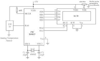
The circuit diagram of the thermometer:

Digital Thermometer circuit Microcontroller
Circuit Diagram of Digital Thermometer using PIC Microcontroller
The output of LM35 Temperature sensor is directly connected to the Analog channel AN0 of the microcontroller. The LCDs are widely used in microcontroller based projects to display the value of parameters or variable and to show input output user data. There are two main types of LCDs mostly used with microcontrollers for this purposes: text based or graphical. The text LCDs are very easy to handle and writing the software coding is also easy, however the graphic LCD involves more code listing and are lit but complex but not too much. Here in this project we are going to use a small text LCD. In this regards the most popular LCD is HD44780 based controller.

Function and connection of LCD
LCD PIN CONNECTIONS and FUNCTIONS
The more pronounced models of LCDs using HD44780 controller are following as example:

  • LM016L:  It is consist of 2 rows × 16 characters in each row, total 32 characters can be display at a time.
  • LM017L:  It is consist of 2 rows × 20 characters in each row, total 40 characters can be display at a time.
  • LM018L:  It is consist of 2 rows × 40 characters in each row, total 80 characters can be display at a time.
  • LM044L:  It is consist of 4 rows × 20 characters in each row, total 80 characters can be display at a time.

The PICC language have built in libraries to handle LCDs based on controller HD44780 and the data/ text can be very easily displayed it using built in functions. The following built in library functions are used to control the LCD with PIC microcontroller using PICC Compiler:

  • lcd init: To initialize the LCD at start of program, when controller is power ON, the code inside this function is executed to initiate the LCD to make it ready for accepting for commands to display user text on user define location of LCD etc.
  • lcd clear: To clear the screen of whole LCD , all previously display text will b washed and the cursor will point to the home location means at the start of LCD.
  • lcd goto: This function is used to bring the cursor at desired location/position
  • lcd write: It is used to send a character to the LCD for display of a single character.
  • lcd puts: It is used to send a text string to the LCD for display of test.

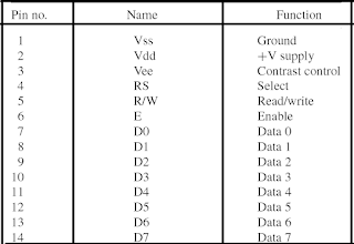
The LCDs based on HD44780 type controller have 14 pins. The following figure shows the pin numbers and their function. The Pin 3 of LCD is used to control the contrast of the display, normally a variable resistor is used with this, but for simplicity it can be directly tied to ground for full contrast. The RS pin of LCD is used to send a control or a text depends on the logic on this pin. When the read or write (R/W) pin of LCD is at logic level 0, a command or a text message can be sent to the LCD. When R/W is at logic level 1, the LCD status can be read. The LCD is enabled when the E pin of LCD is at logic level 0, therefore it is also normally connected to ground for permanent enable condition. Pins D0 to D7 of LCD are the data inputs pins. There are two modes of interface 8 bit or 4 bit mode. The LCD in full 8-bit mode is connected to 8 lines of microcontroller, whereas, or in 4-bit half mode only the upper four data pins are connected to four i/o lines of microcontroller. Usually the 4-bit mode is preferred as it uses fewer pins of microcontroller. In order to use the PICC, pre written library LCD functions, the LCD shall be connected in a predefine hardware connection with microcontroller which are as follows,

Microcontroller Port pin                     LCD pin

RB0                                                        D4

RB1                                                        D5

RB2                                                       D6

RB3                                                       D7

RA2                                                       RS

RA3                                                        E

Software of The Thermometer

//*******************************************************************

//

// DIGITAL THERMOMETER USING LM35 AND PIC 16F877

// ============================

// Author: Dr. Rana

// Date: 17 August 2022

// File: DIGITAL-THERMOMETER.C

// The coding listing in this program will read the raw-data Temperature form a LM35DZ analog

// sensor after one second and then displays the measured raw-data Temperature on an Alphanumeric LCD.

// The microcontroller PIC 16f877 is configured to operate on a 4MHz crystal.

//

//*******************************************************************

#include <pic.h> // PIC Library having all basic definition of PIC Microcontroller

#include <delay.c> // The Delay Libray used to introduce some delay functions in the code listing

#include <lcd.c> // To control LCD, this built in Library or header file is included

#include <stdio.h> // the compiler’s built in library to handle text strings efficiently

// Delay Function of about one second

void wait a second()

{

unsigned int j;

for(j = 0; j < 4; j++)DelayMs(250);

}

// Main Program start here

main(void)

{

const float Volt2number = 5000.0/1024.0; // declaration and unitization of variable

float milliVolt, raw-data, raw-data-one, raw-data-high;

unsigned int raw-data-temp; // declaration and unitization of variable

unsigned char disp[] = "RAW-DATA = ";// declaration and unitization of variable

TRISA = 1; /* RA0 is input, others output */

TRISB = 0; /* PORT B is output */

ADCON1 = 0x8E; /* RA0=analog, RA2,RA3=digital */

ADCON0 = 0x41; /* Configure A/D clock and select channel 0 */

for(;;)// While One function, it be executed as long as the MCU is power ON

{

ADCON0 = 0x45; /* Start A/D conversion */

while(ADCON0 & 4) != 0); /* Wait for conversion */

raw-data-high = ADRESH; /* Read upper 2 bits */

raw-data-one = ADRESL; /* Read lower 8 bits */

raw-data = 256.0*raw-data-high + raw-data-one; /* Raw-data corresponds to Temperature in digital */

milliVolt = raw-data *Volt2number; /* Raw-data corresponds to Temperature in milli-Volt */

raw-data-temp = milli-Volt / 10.0; /* Raw-data corresponds to Temperature in Centigrade. (10milliVolt/C) */

sprintf(disp+7, "%d",raw-data-temp); /* Convert raw-data to Temperature to a string */

lcd puts(raw-data-temp); /* Display raw-data Temperature on LCD */

wait a second(); /* delay of one second */

lcd clear(); /* Clear display */

}// end of while one function

}// end of main function and also end of code listing

Digital Thermometer Using Arduino & LM35 Temperature, temperature sensor using 8051 microcontroller pdf, Components Required: ; 1, Arduino UNO Board ; 2, LM35 Temperature Sensor ; 3, 16x2 LCD Display ; 4, Potentiometer 10K ; 5, Connecting Wires, temperature sensor using microcontroller, Building a digital thermometer using Lm35 and pic18f2580, What is analog temperature sensor? , How to Simplify the Interface between Microcontroller, The µC reads the output code of an analog-to-digital converter (ADC) driven by a thermistor-resistor voltage divider, analog-output temperature sensor, digital thermometer using lm35 and 8051 microcontroller, What is the construction of electronic thermometer?, Thermometer can be easily constructed using a PIC Microcontroller and LM35 Temperature Sensor. LM35 series is a low cost and precision Integrated Circuit, LM35 Temperature Sensor: Build Your Own Digital, digital thermometer project using arduino, What microcontroller is used in thermometer?, how to interface temperature sensor with microcontroller, digital thermometer using arduino and lm35 temperature sensor research paper, How to construct digital thermometer using LM35 and Arduino? ,Design and Implimentation of a Microcontroller Based , Digital Thermometer using a PIC Microcontroller and DS18B20, digital thermometer project without arduino, thermometer using 8051 microcontroller ppt ,digital thermometer project report pdf ,What is the construction and working of temperature sensor? ,The design is in four modules; power supply, temperature sensor, ... In this paper a digital thermometer was designed and constructed using AVR ,digital thermometer using 8051 microcontroller project report ,digital thermometer project report ,What is the construction of electronic thermometer?, Digital Thermometer using PIC Microcontroller and LM35, temperature sensor using pic16f877a microcontroller, How does a temperature sensor work in a microcontroller?, How does an analog temperature sensor work? ,UC using digital thermometer project report ppt, Microcntroller based thermometer using arduino project report, MCU based digital thermometer using arduino pdf ,arduino temperature sensor project pdf