Pages

DESIGNING AUTOMATIC GATES USING MICROCONTROLLERS FOR PARKING

Aim and Objective of Microcontroller based Automation Project:

 The main Aims and Objectives of this project is to design and develop an automatic car parking system having fully automatic gates. The use of automatic gates for various purposes can be seen in many application in different industries as well as in security systems and also at tool plazas. Same is here, we will implement this idea in our automatic car parking system. Introduction of Project: The application of the automatic control systems in different system can be observed rapidly grown during the past few decades. Same as the automatic barrier control system. The manual working or handling of any application has less accuracy as compare to the automated microcontroller based control systems. The project is basically giving an initial theme that how we can approach to an automatic barrier control system using 8051 microcontrollers. “Two gates or doors located at the entrance and exit of car parking will be opened and closed through the use of two stepper motors which be governed by Microcontroller at back of the whole system. Some of the application of automatic door controls are airports, toll gates, railway crossings etc.

 Overview of the Automatic Car Parking System: 

The parking system is based around an At89C51 micro-controller and U-shaped photo sensors. It is quick and efficient in operation. The microcontroller is serially interfaced to the PC using serial port and the RS-232 Transmitter/Receiver. The components like u-shaped Photo sensors, stepper motor and At89C51 microcontroller will be configured to each to have the control of the entire operation of the car parking control system collectively. The seven segment display units along with the serial interface will be responsible to display the number of cars already parked in the parking lot. Block diagram of the system is shown in figure 1 below. 
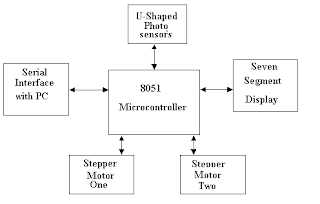
Automated Car Parking System
Block Diagram of The Automated Car Parking System

Basic Components Required for development of Automatic Parking System:

 In the context of design and implementation of car parking control system required the use of following the important components: 

  • Stepper Motor 
  • U-shaped Photo Sensors 
  • Seven segment Display 
  • Serial Interfacing 

The components used in this automation project will be discussed here briefly one by one. 

Stepper Motor

A stepper motor is a digital electrical device used in various electronics application for controlled and precise motion of various rotary devices. The step motor moves under the commands of digital instructions accurately, through a specific electronics control circuit. This is the unique functionality of a step motor. In brief, the step motors are electrical motors which are driven through the digital pulses in contrast to other motors where continuously voltage are applied to have motion. The pulse give to stepper motor is equal one step. The Two stepper motors are used in this project. One is for incoming gate and other is for outgoing gate. To step a motor in a particular direction a specific switching sequences need to be followed. There are two configurations of electric connections with stepper motor: 6-wire configuration and the second is 8-wire configuration. 

U-shaped Photo Sensors

The u-shaped photo sensor is a device has two main electronics components inside it which are emitting-light sources and the detectors. The LED and photo transistor or photo diode are mounted face-to-in the sensor. The collector of the phototransistor acts as an output pin, connected to microcontroller pins. If an object comes between the gap between the LED & photo transistor the light will be blocked. The logic level will be changed on the output of the sensor, indication the interruption. This condition generates required signal which will be read by microcontroller. 
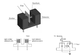
Optocoupler U type sensor
U-shaped input Optocoupler sensor

Seven segment Display

The LED seven-segment display is used in many electronic devices to display useful information to the user of that device. The construction of the seven segments display is very simple as the 7 LEDs are combined into one casing to make a device for the displaying numbers from 0 to 9. The one wire of all the seven LED are kept common. Therefore, these are constructed in two ways, the common anode type or common cathode type. In common anode type display unit, the positive leg of each LED is made internally common and tied to Vcc, whereas the other negative legs are open for external interface. The assembly is reversed for common cathode type units. 
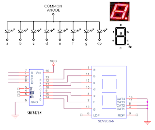
7 segment display
Common anode configuration Seven segment display

Serial Interfacing

The micro-controller is interfaced to the PC by serial port through ICL232 logic level converter. The personal computer and AT89C51 microcontroller are interfaced through RS-232 for serial communication. RS-232 Serial Communication The RS-232 is a serial communication standard which enables data to be transferred in serial form between two devices. The data is transmitted in serial bit stream from one device to another. The parameters specify an RS-232 link between two devices are usually the baud rate, data width, parity and stop bits and are described below. 

  • Baud rate: The baud rate is defined as the number of bits per second. The baud rate determines the quantity of information communicated in a unit time. It may in some where in range of 110 and 76800 bits per second. 
  • Data width: The data width of a byte can be either 8 bits or 7. 
  • Parity: The parity bit in serial communication is used to check the correctness of the transmitted or received data. Parity bit can be zero or one corresponds to even, odd.
  • Stop bits: The stop bit in serial communication is used as the terminator bit.

Serial data is transmitted and received in frames where a frame consists of: 1 start bit, 7 or 8 data bits, Optional parity bit, 1 stop bit. In many applications 10 bits are used to specify an RS-232 frame, consisting of 1 start bit, 8 data bits, no parity bit, and 1 stop bit. For Example, character ‘A’ has an ASCII bit pattern ‘01000001’ and is transmitted. Two types of connectors are used for RS232 communication. These are 25-way (known as DB25) and the 9-pin D-type connector (also known as DB9). 

  • SG: signal ground. This pin is used in all RS-232 cables for ground connection. 
  • RD: Received data. Data is received at this pin. This pin is used in all two-way communication.
  • TD: Transmit data. Data is sent out from this pin. This pin is used in all two-way communication. 
  • RTS: Request to send. This signal is asserted when the device requests data to be send. 
  • CTS: Clear to send. This signal is stated when the device is ready to accept data serially. 
  • DTR: data terminal ready. This signal is asserted to indicate the device is ready. 
  • DSR: Data set ready. This signal indicates, by the device at another end, that is ready. 
  • CD: Carrier detect. This CD shows that a carrier signal has been detected by a modem or device which is connected to the line. 

RS232 Signals Levels A voltage of +3 to+12 indicates an on state, while a voltage of -3 to -12 indicates an off stage. Standard TTL logic devices, including 89c51 microcontroller. Operate with TTL logic levels between the voltages of 0 and +5V. The Voltage level converter ICs convert the voltage levels between the TTL level and RS232 voltage levels. E.g. ICL-232, MAX-232 etc. 

The Hardware Description and Construction of electronics circuit boards

The whole system is consisting of some small electronics board separately developed to make clear understandings of working of system.

Stepper Motor Control Board 

The electronics circuit board to drive stepper motor is designed to handle up to four stepper motors. But the requirement of this project is only the two. Remaining the slot of two stepper motors can be used for the further modification in project. The port 0 of microcontroller is used to drive the above said two motors. The P0.0 to P0.3 drive one motor while P0.4 to P0.7 for second stepper motor. A TTL latch IC is used to latch the logic level of these port pins. The P3.5 is connected to enable of the latch. Figure below shows the complete circuit diagram of stepper motor driver board. An optocoupler is used to have electrical isolation between the motor controller board and the rest of electronics. The microcontroller AT89S51 actually determines the needs and then send the control signal to the stepper motor controller board for appropriate rotation of stepper motor with energizing coil of the stepper motor so that each step of it covers about 1.8 degree of rotation. The current of each motor coil is about 1Amp. There is a diode is used in parallel to the coil of stepper motor to prevent the damage of transistors with high back current due to change in emf of the coil. These diodes setup like this are often known as freewheeling diodes. 

Sensors Board:

This hardware unit or board has six photo sensors. The output pin of every sensor is connected to one pin of the controller. As shown in figure 08 sensors generate a high pulse as beam is cut by ant small object. Three sensors used to operate one motor. Port1 is dedicated to the sensors as shown in figure below. By cutting beam of sensor S1 Motor start rotating in clockwise direction, then cutting the beam of sensor S2 motor stops for some time then start rotating in counter clock wise direction. At the end-cutting beam of S3 motor stops. The second stepper motor will operate the sensors S4, S5 and S6 when operated as discussed earlier. 
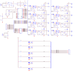
Steper Motor Driver
Stepper Motor Controller and Opto Coupler input Board

Seven Segment Display Board:

 This hardware is used to display the number of cars in the parking lot. The display board has six-segment display units or digits on it. The segment driver IC named SN7447AN which is a TTL IC is used to drive the seven-segment digit along with a three to eight-line decoder to select the corresponding digit. The figure below shows the circuit diagram of the seven-segment board. The Port2 of the Microcontroller is use to operate the display board for appropriate digit display on the respective unit. Serial Interfacing Board The PC placed in the control room for the help of operator will display the useful information about the parking capacity of car parking space in real time. The Microcontroller have input data from sensor and have the basic information of parking which will be transmitted to PC through the use of serial communication as discussed earlier. The circuit diagram of the serial communication board is show along with the display board in figure below.

LED Seven Segment Display Driver and RS-232 serial communication Board

Software description of the project

As we have discussed the hardware of this project has four peripherals section interfaced with the microcontroller. Therefore, the whole software program written for this project for microcontroller At89s51 is consisting of four main routines to make system functional, the subroutines of the program are listed below: 

  • Stepper motor subroutine 
  • Optical Sensor subroutine 
  • Seven segment subroutine 
  • Serial interrupt subroutine 

Stepper Motor Subroutine 

The Port0 of the microcontroller is used for controlling the stepping sequence of stepper motors at the entry and exit gates of car parking system. The Lower Nibble of Port0 of MCU is used for controlling the stepper motor number 01 which is mounted and placed at the entry gate. The Upper Nibble of Port0 is used to control the stepper motor number 02 which is mounted and place at the exit gate. The bits of port0 of MCU are set and reset according to the stepping sequence of each motor as listed in program. There are total six control bits in this sub-routine in which the two control bits are used to select and initiate the operation of stepper motors at the entry or exit gate. The three control bits of the stepper motor has specific function, one bit is used to initiate or select the motor and remaining two bits are used to control the motion. It may be noted that the operation of stepper motors is directly related to the input from sensor which is interpreted in the MCU and execution is accordingly done by passing appropriate commands to motors. 

Optical Sensor Subroutine

Optical sensors are connected to the port1 of the microcontroller. These input signal from these sensors are bases for the suitable initiation to the stepper motor subroutine. Each sensor is installed at a special location for performing a desire task such as to detect a entering vehicle or leaving the parking space, to detect gate current position whether it is fully opened o fully closed or in between the opening and closing position through the implementation of limit switches. The system remains in waiting condition until one of the sensor is triggered by arrival of a car or leaving of any vehicle. The sensors are placed at the entry and exit points of parking area gates to detects the vehicles passing through each gate. The two sensors are used to detect opening limit of each gate and other two to detect closing limit of each gate. When an entry gate sensor give signal then the seven-segment display subroutine is called along with the serial interrupt subroutine. The display unit will update the current number of cars present in the parking area. The count will be incremented correspondingly with entry gate control bit set and reset sequence. When an exit gate sensor is triggered the corresponding control bit will be set and the seven-segment display subroutine will also be called along with the serial interrupt subroutine. This will update the current number of cars present in the parking area and will be display accordingly on local display unit as well as in the computer screen placed in control room for the use of operator. Similarly, the count will decrement in response of the exit gate control bit set and reset sequence. The open limit gate sensors turn the motor in reverse direction after a delay and the close limit gate sensor turns the motor off for entry and exit gate. 

Seven Segment Subroutine 

The Port2 of At89s51 is used for the interfacing of the display unit, the data on port2 will updates the seven-segment display every time the entry or exit gate sensor operates. 

Serial Interrupt Subroutine 

 A SERISR (serial interrupt service routine) is defined and used in the main program. The TxD @ P3.1 and RxD @ P3.0 are used in serial interfacing between PC and Microcontroller. The display of parking position on computer screen is updated serially on the operation of sensors as discussed earlier. The 9600 baud rate and mode 01 for serial interfacing is implemented in this project. Instantly we have used the “Labview” software for serial communication and presentation of display of parking project.

Assembly Language Program Listing For Microcontroller

;================================================
;==================BITS ASSIGNMENTS==============
;================================================
OLG1            REG             P1.0    ;OPEN LIMIT GATE1
CLG1            REG             P1.1    ;CLOSE LIMIT GATE1
G1IL              REG             P1.2    ;GATE1 INTERLOCK
OLG2            REG             P1.3    ;OPEN LIMIT GATE2
CLG2            REG             P1.4    ;CLOSE LIMIT GATE2
G2IL              REG             P1.5    ;GATE2 INTERLOCK
;==================
M1P1            REG             P0.0    ;MOTOR 01 PHASE 1            
M1P2            REG             P0.1    ;MOTOR 01 PHASE 2
M1P3            REG             P0.2    ;MOTOR 01 PHASE 3
M1P4            REG             P0.3    ;MOTOR 01 PHASE 4
M2P1            REG             P0.4    ;MOTOR 02 PHASE 1            
M2P2            REG             P0.5    ;MOTOR 02 PHASE 2
M2P3            REG             P0.6    ;MOTOR 02 PHASE 3
M2P4            REG             P0.7    ;MOTOR 02 PHASE 4
;==================
A_SSD           REG             P2.4
B_SSD           REG             P2.7
C_SSD           REG             P2.6
D_SSD           REG             P2.5
;==================
A_SEL           REG             P2.2
B_SEL           REG             P2.0
C_SEL           REG             P2.1
E_SEL           REG             P2.3
;==================
ENB             REG             P3.5    ;ENABLE 74LS245
BUZ             REG             P3.4    ;BUZZER
;================================================
;=================FLAG ASSIGNMENTS===============
;================================================
FLG1            REG             00H     ;BIT 0 OF 20H
FLG2            REG             01H     ;BIT 1 OF 20H
FLG3            REG             02H     ;BIT 2 OF 20H
FLG4            REG             03H     ;BIT 3 OF 20H
FLG5            REG             04H     ;BIT 4 OF 20H
FLG6            REG             05H     ;BIT 5 OF 20H
BINC            REG             06H     ;BIT 6 OF 20H
BDEC            REG             07H     ;BIT 7 OF 20H

B_0             REG             08H     ;BIT 0 OF 21H
B_1             REG             09H     ;BIT 1 OF 21H
B_2             REG             0AH     ;BIT 2 OF 21H
B_3             REG             0BH     ;BIT 3 OF 21H
B_4             REG             0CH     ;BIT 4 OF 21H
B_5             REG             0DH     ;BIT 5 OF 21H
B_6             REG             0EH     ;BIT 6 OF 21H
B_7             REG             0FH     ;BIT 7 OF 21H
;================================================
;================BYTE ASSIGNMENTS================
;================================================
OUTPRT          REG             P0      ;PORT ZERO
DISPRT            REG             P2
DATREG           EQU             21H
DLYREG1         EQU             30H
DLYREG2         EQU             31H
DLYREG3         EQU             32H
DLYREG4         EQU             33H
D_UNI               EQU             34H
D_TEN              EQU             35H
D_HUN             EQU             36H
CNTR                EQU             37H
DISPREG          EQU             38H
;================================================
;==================DIRECTIVES====================
;================================================
                ORG             00H     ;RESET
                LJMP            INI
                ORG             0BH
                LJMP            T0ISR
                ORG             23H
                LJMP            SERISR
                ORG             30H
;================================================
;===========INITIALIZATION ROUTINE===============
;================================================
INI:
                MOV             D_UNI,#00H
                MOV             D_TEN,#00H
                MOV             D_HUN,#00H
                MOV             OUTPRT,#00H
                CLR             ENB
                CLR             FLG1
                CLR             FLG2
                CLR             BUZ
                CLR             BINC
                CLR             BDEC
                CLR             E_SEL
                CLR             C_SEL
                MOV             DLYREG1,#FFH
                MOV             DLYREG2,#0FH
                MOV             DLYREG3,#FFH
                MOV             DLYREG4,#0FH
                MOV             TMOD,#21H       ;16 BIT TIMER MODE
                MOV             TL0,#DFH
                MOV             TH0,#B1H
                MOV             TH1,#-3
                MOV             SCON,#50H
                MOV             IE,#92H
                MOV             A,CNTR
                MOV             SBUF,A
                SETB            TR1
                SETB            TR0
;================================================
;================MAIN ROUTINE====================
;================================================
MAIN:
                CALL            INR_0    ;INPUT ROUTINE
                CALL            INR_1    ;
                CALL            INR_2
                CALL            INR_3
                CALL            M1R     ;MOTOR1 ROUTINE
                CALL            M2R
                CALL            IDR     ;INCREMENT/DECREMENT ROUTINE
                CALL            DIVR
                LJMP            MAIN
;================================================
;========INPUT ROUTINE 01 FOR FOR MOTOR 1========
;================================================
INR_0:
                JB              G1IL,INR1
                JB              FLG1,INR2
                RET
INR1:
                SETB            FLG1
                RET
INR2:
                JNB             FLG1,INREXT1
                DJNZ            DLYREG1,INREXT1
                DJNZ            DLYREG2,INREXT1
                SETB            BINC
                CLR             FLG1
INREXT1:
                RET
;================================================
;=========INPUT ROUTINE 02 FOR MOTOR 1===========
;================================================
INR_1:
                JB              OLG1,INR3
                JB              CLG1,INR4
                RET
INR3:
                SETB            FLG2
                CLR             FLG3
                RET
INR4:
                SETB            FLG3
                CLR             FLG2
                RET
;================================================
;========INPUT ROUTINE 01 FOR FOR MOTOR 2========
;================================================
INR_2:
                JB              G2IL,INR1_1
                JB              FLG4,INR2_2
                RET
INR1_1:
                SETB            FLG4
                RET
INR2_2:
                JNB             FLG4,INREXT2
                DJNZ            DLYREG3,INREXT2
                DJNZ            DLYREG4,INREXT2
                SETB            BDEC
                CLR             FLG4
INREXT2:
                RET
;================================================
;===========INPUT ROUTINE 02 FOR MOTOR 2=========
;================================================
INR_3:
                JB              OLG2,INR3_3
                JB              CLG2,INR4_4
                RET
INR3_3:
                SETB            FLG5
                CLR             FLG6
                RET
INR4_4:
                SETB            FLG6
                CLR             FLG5
                RET
;================================================
;===========MOTOR NUMBER 01 ROUTINE============
;================================================
M1R:
                JB              FLG1,M1R_1
                JB              FLG2,M1R_2
                RET
M1R_1:
                JNB             FLG2,M1R_3
                CLR             M1P1
                CLR             M1P2
                CLR             M1P3
                CLR             M1P4
                RET
M1R_3:
                CALL            M1CLK
                RET
M1R_2:
                JNB             FLG3,M1R_4
                CLR             M1P1
                CLR             M1P2
                CLR             M1P3
                CLR             M1P4
                RET
M1R_4:
                CALL            M1CCLK
                RET
;================================================
;======MOTOR NUMBER 01 CLOCK WISE==============
;================================================
M1CLK:
                SETB            M1P1
                CLR             M1P2
                CLR             M1P3
                CLR             M1P4

                CALL            DLYRM1

                CLR             M1P1
                SETB            M1P2
                CLR             M1P3
                CLR             M1P4

                CALL            DLYRM1

                CLR             M1P1
                CLR             M1P2
                SETB            M1P3
                CLR             M1P4

                CALL            DLYRM1

                CLR             M1P1
                CLR             M1P2
                CLR             M1P3
                SETB            M1P4

                CALL            DLYRM1

                CLR             M1P4
                RET
;================================================
;===MOTOR NUMBER 01 COUNTER CLOCK WISE========
;================================================
M1CCLK:
                SETB            M1P4
                CLR             M1P2
                CLR             M1P3
                CLR             M1P1

                CALL            DLYRM1

                CLR             M1P4
                SETB            M1P3
                CLR             M1P2
                CLR             M1P1

                CALL            DLYRM1

                CLR             M1P1
                CLR             M1P3
                SETB            M1P2
                CLR             M1P4

                CALL            DLYRM1

                CLR             M1P3
                CLR             M1P2
                CLR             M1P4
                SETB            M1P1

                CALL            DLYRM1

                CLR             M1P1
                RET
;================================================
;=================DELAY ROUTINE==================
;================================================
DLYRM1:
                MOV             R0,#0FH
W1:
                MOV             R1,#FFH
W2:
                
                DJNZ            R1,W2
                DJNZ            R0,W1
                RET
;================================================
;=========MOTOR NUMBER 02 ROUTINE==============
;================================================
M2R:
                JB              FLG4,M2R_1
                JB              FLG5,M2R_2
                RET
M2R_1:
                JNB             FLG5,M2R_3
                CLR             M2P1
                CLR             M2P2
                CLR             M2P3
                CLR             M2P4
                RET
M2R_3:
                CALL            M2CLK
                RET
M2R_2:
                JNB             FLG6,M2R_4
                CLR             M2P1
                CLR             M2P2
                CLR             M2P3
                CLR             M2P4
                RET
M2R_4:
                CALL            M2CCLK
                RET
;================================================
;========MOTOR NUMBER 02 CLOCK WISE============
;================================================
M2CLK:
                SETB            M2P1
                CLR             M2P2
                CLR             M2P3
                CLR             M2P4

                CALL            DLYRM2

                CLR             M2P1
                SETB            M2P2
                CLR             M2P3
                CLR             M2P4

                CALL            DLYRM2

                CLR             M2P1
                CLR             M2P2
                SETB            M2P3
                CLR             M2P4

                CALL            DLYRM2

                CLR             M2P1
                CLR             M2P2
                CLR             M2P3
                SETB            M2P4

                CALL            DLYRM2

                CLR             M2P4
                RET
;================================================
;=====MOTOR number 02 COUNTER CLOCK WISE========
;================================================
M2CCLK:
                SETB            M2P4
                CLR             M1P2
                CLR             M1P3
                CLR             M1P1

                CALL            DLYRM2

                CLR             M2P4
                SETB            M2P3
                CLR             M2P2
                CLR             M2P1

                CALL            DLYRM2

                CLR             M2P1
                CLR             M2P3
                SETB            M2P2
                CLR             M2P4

                CALL            DLYRM2

                CLR             M2P3
                CLR             M2P2
                CLR             M2P4
                SETB            M2P1

                CALL            DLYRM2

                CLR             M2P1
                RET
;================================================
;=================DELAY ROUTINE==================
;================================================
DLYRM2:
                MOV             R2,#0FH
W3:
                MOV             R3,#FFH
W4:
                
                DJNZ            R3,W4
                DJNZ            R2,W3
                RET
;================================================
;==========INCREMENT DECREMENT ROUTINE===========
;================================================
IDR:
                JB              BINC,IDR1
                JB              BDEC,IDR3
                RET
IDR1:
                MOV             A,CNTR
                CJNE            A,#FFH,IDR2
                MOV             CNTR,#FFH
                CLR             BINC
                RET
IDR2:
                INC             CNTR
                CLR             BINC
                RET
IDR3:
                MOV             A,CNTR
                CJNE            A,#00H,IDR4
                MOV             CNTR,00H
                CLR             BDEC
                RET
IDR4:
                DEC             CNTR
                CLR             BDEC
                RET
;================================================
;================DIVISION ROUTINE================
;================================================
DIVR:
                MOV             A,CNTR
                MOV             B,#0AH
                DIV             AB
                MOV             D_UNI,B

                MOV             B,#0AH
                DIV             AB
                MOV             D_TEN,B

                MOV             D_HUN,A
                RET
;================================================
;==============SERIAL INTR. ROUTINE==============
;================================================
T0ISR:
                PUSH            A
                CLR             TR0
                MOV             TL0,#DFH        ;20mSEC
                MOV             TH0,#B1H

                MOV             A,D_UNI   ;SEND THE UNIT PLACE NO.
                CALL            DSHIFT    ;TO ADJUST PIN CONFIG
                ANL             A,#F0H    ;TO SEND ONLY UPPER NIBBLE
                MOV             DISPRT,A  ;MOVE DATA TO P2
                SETB            A_SEL
                SETB            B_SEL     ;INITIALIZE UNIT PLACE SEG(3)
                CALL            DSPDLY    ;CALL DELAY

                MOV             A,D_TEN   ;SEND THE TENTH PLACE NO.
                CALL            DSHIFT
                ANL             A,#F0H
                MOV             DISPRT,A
                CLR             A_SEL
                SETB            B_SEL     ;INITIALIZE TENTH PLACE SEG(2)
                CALL            DSPDLY

                MOV             A,D_HUN   ;SEND THE HUNDREDTH PLACE NO.
                CALL            DSHIFT
                ANL             A,#F0H
                MOV             DISPRT,A
                SETB            A_SEL
                CLR             B_SEL
                CALL            DSPDLY
                CLR             A_SEL     ;INITIALIZE HUNDREDTH PLACE SEG(1)
                CLR             B_SEL
                POP             A
                SETB            TR0
                RETI
;================================================
;================DATA SHIFT ROUTINE==============
;================================================
DSHIFT:
                MOV             DATREG,A        ;21H=DATAREG
                MOV             C,B_0   
                MOV             B_4,C   
                MOV             C,B_1
                MOV             B_7,C
                MOV             C,B_2
                MOV             B_6,C
                MOV             C,B_3
                MOV             B_5,C
                MOV             A,DATREG
                RET
;================================================
;===================DISPLAY DLAY=================
;================================================
DSPDLY:
                MOV             R7,#FFH
DW1:
                DJNZ            R7,DW1
                RET
;================================================
;====================SERIAL INT.=================
;================================================
SERISR:
                PUSH            A
                JNB             TI,REC
                MOV             A,CNTR
                MOV             SBUF,A
                CLR             TI
                POP             A
                RETI
REC:
                JNB             RI,SEREXT
                CLR             RI
SEREXT:
                POP             A
                RETI
;================================================
                END
                

automatic gate control system pdf The microcontroller based automatic gate control is a better solution. automatic gate opening and closing system What are the examples of microcontroller based system? This system consists of a set of sensors connected to a stepper motor through an 8-bit microcontroller (AT89S52). What are the different designs of automated gates? automatic gate opening system project pdf Are microcontrollers used in control systems? Microcontroller based automate controller is a project design of a system that is used in operating a gate automatically. Can you make your own automatic gate? What is the use of logic gate in microcontroller? electric gate entry systems electric gate keypad wiring What is microcontroller based system design? CONSTRUCTION OF A MICROCONTROLLER BASED GATE motor for automatic sliding gate Microcontroller Based Bi-directional Vehicle Counter diy automatic sliding gate sliding gate electric Microcontroller based Automatic Railway Gate Control automatic gate opening and closing system electric gate wiring diagram What mechanism is used in automatic gates? sliding gate machine automatic sliding gate What are the components of an automatic gate? electric swing gates

No comments:

Post a Comment

Please ask if you have any question regarding the programming of MCU, or have any problem in development of your electronics project. microcontroller51.blogspot.com