Ultrasonic Sensor Utilization for Water Level Measurement with PIC16F877A Microcontroller
The various types of industrial applications often require the use of the data acquisition systems for the measurements of fluid volume and level. There are many techniques such as sensors based on capacitance changes, optical fiber, surface Plasmon resonance, Doppler Effect and wedge waves to measure the level of any fluid in a container at various places like process industry or elsewhere. All of these techniques there are certain limitation associated with them and advantages over each other of course. Therefore need arises to develop better techniques which gives better results. The collection of useful data from fluid tanks has very important significance in all industrial applications i.e. the public water supplies & storage tanks, Automatic water treatment plants, Process industry tanks, cooling towers, fish aquariums, oil tanks, irrigation, flow control application fuel containers and reverse osmosis RO systems, etc.
Here we are using ultrasonic Technique for the measurement of level of fluid in a tank by using microcontroller. The water level measurement system being developed here also can control the level of the tank automatically and even can provide early warning of reduced or over filled water level. Therefore we can say that this system has following three main features:
1. Measurement of level of fluid in a container and provision of local display
2. Control of flow of fluid using suitable pump
3. Early warning system if level is abnormal
The heart of the project is Microcontroller PIC16F877A which is programmed so that all the above mentioned features are successfully fulfilled. The sensor circuit provides the measurements in the form of electrical signal corresponding to reflected echoes from the surface of the water. The ultrasonic sensor as named by manufacture the PING sensor can detect the changes in the water level and generated the electronics signal accordingly which is read by microcontroller and does the further processing on it. The processing being carried out inside microcontroller will be now discussed in detailed, so that students can understand it very easily.
Designing of Liquid Level Measurement
System:
In
this project a PIC16F877A microcontroller is being for the monitoring and
control of water level in a small tank using an ultrasonic sensor and water
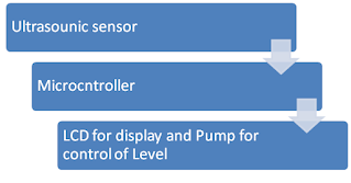
pump. The flow diagram of the level measurement system is described in figure below.
However we will discuss the key components one by one.
1. Ultrasonic PING Sensor
The ultrasonic sensor is a cost effective solution for the level measurement system and it is easily available in market also. It is used in many engineering applications and process industry as well. This sensor converts electrical energy as a function of acoustic waves with high frequencies by detecting the reflection from the surface of obstacles. Therefore here the use of ultrasonic sensor is to detect the water surface by echo pulses. The ultrasonic sensor is useful for the application having range from 02 cm to 03 m.
2. PIC16F877A Microcontroller
The PIC16F877A
microcontroller is an embedded integrated circuit IC chip having all basic
features of microcontroller like ADC, Ram, Rom, EEPROM and peripheral
interface-able input/ output pins etc, manufactured by Microchip Technology. Therefore
we can say that it integrates many functional and featured subsystems on to
single chip. The microcontroller PIC16F877A has five inputs/ outputs ports having
total 33 pins, 10-bit ADCs, and it operates at 4 to 20 MHz clock frequency. The
microcontroller PIC16F877A is used in many digital monitoring and control applications
because of its inherent features like low cost, availability, low energy
consumption, powerful interrupt structure, and due to flash memory for
facilitation in programming.
The
circuit around microcontroller PIC16F877A includes the electrical connections
to the ultrasonic sensor, DC motor circuit (Water Pump), alarm circuit (Buzzer)
and LCD display unit along with its basic components like crystal, capacitor
and power on rest.
The circuit diagram of level measurement system using microcontroller is described in figure below.
 |
Block Diagram for electrical components connection with microcontroller |
Flow of information:
The electrical
signal from ultrasonic sensor goes to microcontroller pins. The level of the
water is calculated from the time of the reflection of eco pulses. The level of
the water is displayed on LCD. The DC motor circuit is connected to an output
pin of the PIC using a transistor and a relay. The alarm circuit i.e. buzzer is
connected to an output pin of the PIC with a light emitting diode (LED). The
LCD display unit consisting of two lines and 32 characters is connected to the
output port of the PIC for the display of three important parameters i.e. water
level, volume of water in tank and temperature of the water. If the level is
less than the desired level then relay is operated and motor is turned ON. On
reaching the desired level the water pumps is switched OFF using relay
operation. The buzzer is operated only if the level is not increasing due to
any leakages or pump is not operated properly. To avoid over flow of incase
relay is not working and pump is not switching OFF, then again buzzer sounds.
The Volume of water in tank is real time calculated and displayed on the screen.
3. Software
Description
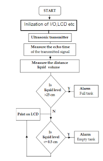
The
software flowchart for the microcontroller PIC for the level measurement system
is described in figure below. The programmed of this project is performed using
PicBasic language on Proton plus IDE (Proton Integrated Development
Environment). The coding of microcontroller is very interesting and easy in Proton
IDE as it is a high level programming language. It used to write basic language
codes for many microcontrollers. On the completion of the machine code file which
is generated from Proton IDE, it is loaded or burnt into the PIC microcontroller
memory using the USB programmer. Then the testing of measurement and control
system starts.
 |
| Water Level measurement system flow Diagram |
Testing and results
The result
shows that fabricated measurement system is accurate, portable, easy to use,
easy to program, cost effective, and low power consumption. It is learnt that
the variation in ambient temperature can introduce some variation in
measurements. So the measurement of temperature is suggested and its
compensation may be worked out in the results. If the distances are greater
than 3 m then the noise is introduced and results can be affected. The maximum
error is approximately 0.1 cm for the level measurement which can be adjusted
by the compensation of the environmental temperature conditions and use of
better detection range sensor.
Keywords: Non-contact water level and volume measurement system, MicroChip PIC16F877A Microcontroller, ultrasonic PING sensor range of ultrasonic sensor, ambient temperature influence on the measurement of level of fluid, how to measure volume of the fluid using ultrasonic transducers.
No comments:
Post a Comment
Please ask if you have any question regarding the programming of MCU, or have any problem in development of your electronics project. microcontroller51.blogspot.com