Pages

Pulse rate Sensor to monitor heart beat rate of human

 Introduction of heart rate monitoring sensor:

To monitor the heart rate or pulse rate of any human body, a dedicated sensor is required. The sensor is basically a device which convert the information of blood flow in vain of body into electrical signal. The signal generated from pulse rate sensor are then process further to interface with microcontroller or microprocessor of Arduino board. Where the digital signal are analyzed and then results are displayed using any convenient means of display like LED display or using LCD display. Therefore we can say that the Pulse Sensor is a especially designed device which is ready for plug and play to measure the heart rate with help of any kind of microcontroller like AVR on Arduino board or Microchip PIC or Atmel 8051 family. This sensor is used by electronics engineering students, professional engineers, software engineers, embedded project developers to easily include the live data of heart rate into projects. There are variety of sensors available for this purpose. The pulse monitoring sensor are usually fixed or attached with help of a clip onto a fingertip or sometimes it can be used on earlobe to get the heart rate data from the body of human.

Principle of construction of Heart Rate Sensors:

The important point of in the discussion regarding the construction of heart arte sensor is that the technique used for the detection of pulse rate is non-invasive type of detection or measurement. These sensors are consisting of optical electrical devices. The majority of the optical heart rate sensor do have f an electronic circuit built-in with them in addition to sensing element to proper shape the electronics signal so that these could be easy interfaced with microcontroller or any digital signal processing device. The operation of the sensors starts with the monitoring of heart beat by clipping these onto a fingertip.

The working principle involved in the working of the Heart beat Sensor is Photo-ple-thysmo-graph. This principle in based to detect the changes in the volume of blood in apart of body like finger. The volume of blood is measured by the variation in the intensity of the light passing or blocked through that organ. The source of light in a heart beat sensor is usually an IR LED and the detector may be of any light intensity Detector like a Photo Diode, a Light Dependent Resistor (LDR) or a Photo Transistor. These two parts work tighter to form an understandable electronics signal.

Parts of pulse sensor:

Parts of a typical pulse rate sensor are basically two;

1.   IR transmitter: The function of IR transmitter is to emit IR which will be used to detect the blood in veins. Basically the media used for the detection of pulse is Infra-Red Radiations.

2.   IR receiver: The function of the IR receiver is to collect the IR passes through the finger. Some of the IR will be blocked when blood passes through the veins. The difference in the intensity will be actually the determination of pulse.

Types of pulse sensor:

There are two techniques which are used for the detection of heart beat;

1.     Reflection Based Detection of Heart Beat:

In this method the light or IR radiation is emitted from IR transmitter and received by IR receiver or photo diode or photo transistor. The light source (IR Transmitter) and the detector (Photo Transistor) are place at same side of a finger or organ (adjacent to each other). The finger of the person is placed in front of the transmitter and receiver. The light is reflected through the finger and a portion of it is blocked and rest of the light passed when blood sticks in veins. The light is shining on the finger and the part reflected back to photo transistor is measured. The quantity of light varies with the amount of blood in veins of finger. As the quantity of blood changes significantly in corresponding the heart function continuously. As a result the pulses are formed through the photo diode or photo transistor end.
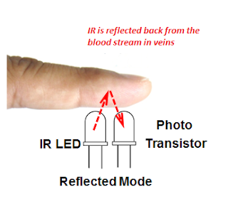
Heart beat, Pulse rate Sensor Construction
 Reflection Based Detection of Heart Beat


2.     Transmission Based Detection of Heart Beat:

In this method the light or IR radiation is emitted from IR transmitter and received by IR receiver or photo diode or photo transistor. The light source (IR Transmitter) and the detector (Photo Transistor) are place facing each other and the finger of the person is placed in between the transmitter and receiver. The light is passed through the finger and a portion of it is block when blood sticks in veins. The light is shined and passes through the finger which is directly relates to the quantity of blood in vein at that time. As we know that the quantity of blood always changes, as a result we get pulse at the light collection device which is in our case the photo-transistor or photo-diode. This is a continuous process of up and down as a function of blood pumped into the finger.
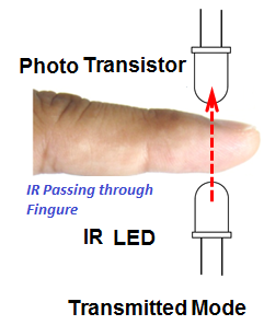
Pulse rate Monitor, Heart Beat Pulse rate sensor
Transmission Based Detection of Heart Beat


Working of Heart beat Sensor with an electronics circuit # 1:

So far we have discussed the theory of working of a pulse sensor. Now we should move to its particle used. In fact the pair of light emitting device and light sensing device are not all the components to get the desired output. We attach some of analog electronics components to make them working. Here we will discuss the construction a simple circuit in which we could be able to detect a pulse using above discussion about the sensor. Therefore we can say that a typical Heart beat Sensor will be consisting of detection based devices along with electronics circuit. The detection part of the Heart beat Sensor will have an IR LED and a Photo Diode/ transistor placed in a clip. The electronics circuit will be consisting of an Op-Amp along with a few other analog electronics components like resistor & capacitors. This electronics circuit will help us to connect the detection part of sensor to signal processing unit like a Microcontroller. The working of the Heart Beat sensor is easily and becomes more interesting when we do a detailed study of the circuit diagram.
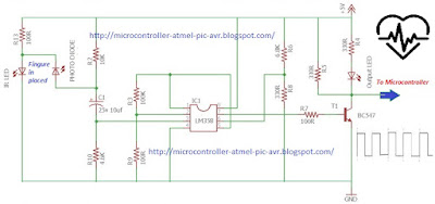
Circuit diagram heart beat sensor, detection pulses
Obtaining Electrical Signal from Heart Beat Sensor


The circuit diagram shown in above figure is based on assumption that the clip sensor part or detection part is attached with the finger. When the heart beat sensor have finger in place between the detectors the pulses are started to detect. As we have already discussed that with every heart beat the amount of blood in the finger will change from minimum to maximum level in the vein. The light emitted from the IR LED on passing through the finger get interactions with the blood quantity. The amount of light managed to pass through the obstacle of blood will be thus detected by the Photo Diode. The amount of light will be the function of amount of blood in vein as a result a changing electrical signal will be available at the photo diode terminal which is then processed through the use of OP-AMP. Here we will use LM358 OP-AMP which is consisting of two op-amp inside a single ship. The output of the photo diode is feed to the non–inverting input of the first op–amp through a capacitor. The use of capacitor at this stage is to block the DC Components of the signal coming from the detection unit. The amplification factor of at this stage is kept around 1001. It is sufficient to amplify the week signal to a level which is desirable. The output of first non-inverting amplifier is feed to second op-amplifier which is built in a comparator mode. The output of second op-amplifier (Comparator0 is used to feed to a transistor to have train of pulses as shown in the circuit diagram above. It may be noted that the construction of this circuit is very simple and efforts are made to use the general purpose components which are easily available in local electronics market or on a radio shop. For example the use of op-amp LM358, the transistor could be any NPN like c828 or BC 547.

Working of Heart beat Sensor with an electronics circuit # 2: 

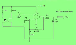
The above circuit has been built in order to have response from optical sensor used to monitor the heart rate pulses as discussed earlier. The only difference is that it is very simple circuit as compared to previous one but it has very good results too.  
Optical sensor for heart rate Monitor
Interface of optical heart rate sensor


In this circuit we are using the IR transmitter coupled with the photo transistor. Again it is the assumption that the finger is placed in between the optical transmitter and optical receiver so that the light have obstacle with blood. For the optical sensor assembly (U2), we used a reflective optical sensor. This sensor has transistor output. Coming to the Op-Amp again we can use the LM358 or Lm 741 as per our convenient choice. But I think for the sake of experiments the results of LM358 are good enough. It is to be noted that the light of the LED is at the peak emitter wavelength 950 nm. The Designers or engineers normally use a range between 700 nm (Red light) to 1000 nm (infrared light) for biological instruments. The light beam have to cross the narrow parts of the body like a fingertip or an earlobe or the lower lip therefore use of this range of light is safe and workable.
PIC 18f452 Battery Internal Resistance Monitor plus desulfator

 Part-3: Battery Tester based on Microcontroller

Construction of battery health Monitor and battery desulfator:

As it has been explained in previous two posts and the name of project also describes that the actual project has two main parts and associated functions.

1. Battery Heath Monitor 

2. Desulfator

Now we will discuss its construction in detail. This project is constructed using microcontroller PIC18452. It has been programmed and the code of the project has been written in basic language and compiled using proton PIC basic complier. The program or code listing is provided in the end of this post.

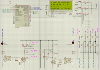
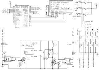
Circuit diagram of the microcontroller based two in one project of battery performance monitor or tester and desulphator is as below.

PIC 18f452 Battery Internal Resistance Monitor plus desulfator
Circuit diagram of Microcontroller based battery internal resistance Monitor

There are Four Segments of the schematic shown in above figure:

1. The Interface of Microcontroller with LCD

2. For adjustment of parameters, the provision of three input push button

3. The measurement of voltages at various stages of project during operation

4. Power module of battery tester which is again consisting of two parts:

        (a) The battery Tester side, which left side of power module section

        (b) The desulfator power section which is at the right side of power module

These will be discuss one by one in detail in below sub-section of this post. Various components used in each section will be introduced and their functionality will be explained as under.

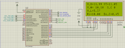
Microcontroller Project Schematic Part-1: 18f452 interfacing with 4-lines 20-Character LCD:

In the first part of whole schematic of this microcontroller project, we will discuss the interfacing of LCD with the PIC Microcontroller which is 18F452. The LCD we are using here in this battery tester cum desulphator is a large LCD which is consisting of Four Lines and each line will have twenty Character spacing. The various parameter will be display at different lines of LCD using microcontroller. The alpha-numeric LCD is interfacing using standard four line interface method as shown in the figure below:

4-line-20 characters LCD-Interface PIC18f452
Microcontroller interfacing LCD for Battery Tester Project

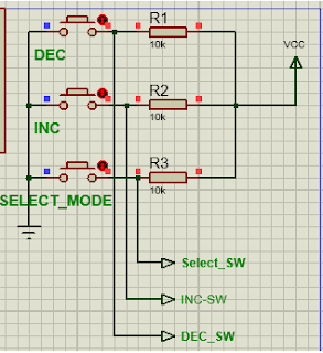
Microcontroller Project Schematic Part-2: 18f452 interfacing with Three Push Buttons:

Three push button have been provided to user for the adjustment of values of critical parameters to be adjusted according to the needs of user real time. These Push buttons are as under:

1. The Setting Selection Mode Switch

2. To increase the parameter values, the ICREMENT Button

3. To decrease the parameter values, the DECREMENT Button

The push switches are pull-up with 10kohm resistors and when press the logic zero is transmitted to microcontroller which is sensed during key-button scanning and the function is performed as per request of user of battery tester at that time, as shown in figure below:

key-switch-interface with microcontroller
Three push button with 18F452 PIC Microcontroller

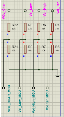
Microcontroller Project Schematic Part-3: Analog Voltages Measurement Interface to Microcontroller:

As the battery Attached for testing may have voltage 6V, or 12V, or 24V which are larger to be interface with microcontroller which accept voltage up to 5v. Therefore voltage divider is used as shown in the figure below: Two resistor are used one is 33Kohm and second is 10Kohm which divide the 12V divided by a factor of approximately 3.3 which is in acceptable range. If user have to interface larger battery the values of above resistor can be re-adjusted and factor used in program as well.


Voltage Divider Circuit Diagram

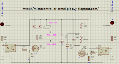
Microcontroller Project Schematic Part-4: Power Module of Battery Tester and Battery Desulfator:

The N-Channel MOSFET Transistor , shunt resistor of 0.05Ohm, is used in Battery Tester side. Whereas The N-Channel MOSFET Transistor, two inductors, diode, capacitor is used in desulphator side of power module as shown in figure below. The battery is at the center of these two type of interfaces. It may be noted that only one function is performed at a time. It means that when we are measuring the internal resistance, the desulfator part is turned off. At an other time when the desulfation of battery is in progress the measurement of internal resistance is switched off. So that each function is performed independently without interference to each other. In this way the results are achieved perfectly.

PIC Microcontroller 18F452 Battery Tester CUM battery Desulfator
Battery Tester CUM battery Desulfator

Complete circuit diagram of the battery tester project:

Battery Tester Complete Schematic Circuit Diagram using PIC Microcontroller


Programming of Battery Tester:

The program is written in PIC Basic Language and compile using proton basic compiler, the code listing is provided as under:

    Device = 18F452
    Declare Xtal = 4

    Config_Start
    OSC = HS         ' Oscillator Selection HS
    OSCS = Off       ' Osc. Switch Enable Disabled
    PWRT = On        ' Power-up Timer Enabled
    BOR = Off        ' Brown-out Reset Disabled
    BORV = 42        ' Brown-out Voltage 4.2v
    WDT = Off        ' Watchdog Timer Disabled
    WDTPS = 128      ' Watchdog Postscaler 1:128
    CCP2MUX = On     ' CCP2 MUX Enable (RC1)
    STVR = On       ' Stack Overflow Reset enabled
    LVP = Off        ' Low Voltage ICSP Disabled
    Debug = Off      ' Background Debugger Enable Disabled
    CP0 = Off        ' Code Protection Block 0 Disabled
    CP1 = Off        ' Code Protection Block 1 Disabled
    CP2 = Off        ' Code Protection Block 2 Disabled
    CP3 = Off        ' Code Protection Block 3 Disabled
    CPB = Off        ' Boot Block Code Protection Disabled
    CPD = Off        ' Data EEPROM Code Protection Disabled
    WRT0 = Off       ' Write Protection Block 0 Disabled
    WRT1 = Off       ' Write Protection Block 1Disabled
    WRT2 = Off       ' Write Protection Block 2 Disabled
    WRT3 = Off       ' Write Protection Block 3 Disabled
    WRTB = Off       ' Boot Block Write Protection Disabled
    WRTC = Off       ' Configuration Register Write Protection Disabled
    WRTD = Off       ' Data EEPROM Write Protection Disabled
    EBTR0 = Off      ' Table Read Protection Block 0 Disabled
    EBTR1 = Off      ' Table Read Protection Block 1 Disabled
    EBTR2 = Off      ' Table Read Protection Block 2 Disabled
    EBTR3 = Off      ' Table Read Protection Block 3 Disabled
    EBTRB = Off      ' Boot Block Table Read Protection Disabled
Config_End
    
    Declare LCD_DTPin = PORTD.4
    Declare LCD_ENPin = PORTD.2
    Declare LCD_RSPin = PORTD.3
    
    Declare LCD_Interface = 4               ' 4-bit Interface
    Declare LCD_Lines = 4                   ' 2-Line LCD
    Declare LCD_Type = 0                    ' Alphanumeric LCD type

    Symbol I_R = PORTC.3  'DEC_SWITCH
    
    Symbol B1 = PORTC.5 ' Select_MODE_Switch
    Symbol B2 = PORTC.6 ' INC_SWITCH
    Symbol B3 = PORTC.7  'DEC_SWITCH
    
    TRISD = %00000000  'All OUTPUT
    TRISC = %11110000  '// 0 t0 3 output and 4 to 7 input

    Declare Adin_Tad = FRC              ' Set clock source (x/FOSC or FRC)
    Declare Adin_Stime = 150            ' Set sampling time (in uS)
    Declare Adin_Res = 10
    ADCON1 = %10000000                  ' Set PORTA analog and right justify result
    Dim     Vol_Un_LOAD     As Word     ' Volatge at termminal without load
    Dim     Vol_Ter         As Word     ' 10-bit result of A/D conversion for Volatge at battery terminal
    Dim     Vol_High        As Word     ' 10-bit result of A/D conversion for Voltage at high side of shunt resistor
    Dim     Vol_Low         As Word     ' 10-bit result of A/D conversion For Voltage At low side of shunt resistor
    Dim     Vol_Charge      As Word     ' 10-bit result of A/D conversion For Voltage At charging side of shunt resistor
    Dim     R_inT           As Float    ' Internal Resistance measurement 
    Dim     Dis_C           As Float     ' Discharge current
    'Dim     Char_C          As Float     ' charging Current
    'Dim     d               As Byte
    Dim     mode_op         As Byte      ' The two mode of functions are selected by this variable
    Dim     mode_0_count     As Byte     ' The times to function each paert of project
    Dim     secondary_cycle_count As Byte ' Time slice
    Dim duty_cycle          As Byte       ' PWM DUTY CYCLE valraible
    Dim cycle_count         As Byte       ' Program CYCLE are counted and displayed on LCD
    I_R = 0 ' Internal Resistance measuremtn Signal OFF
    ''''' INITIAL WELLCOME MESSAGE'''''''''
    Print At 1,1, "Wellcome..DeSulfator"
    Print At 2,1, " Battery Project"
    Print At 3,1, "microcontroller-atmel-"
    Print At 4,1, "pic-avr.blogspot.com"
    DelayMS 1000   ' One Second Time delay
    Cls        ' Clear The LCD DISPLAY
 ''' INITIALIZATION of LOCAL Variables
     mode_op = 0
     secondary_cycle_count = 0
     mode_0_count = 5
 ' for a PIC16F877, 
 'Channel 1 is CCP1 which is pin PortC.2. 
 'Channel 2 is CCP2 which is pin PortC.1.
' Start loop, reads temperature. Loop forever

'''''' Main program Starts here'''''''''''
    While 1 = 1
    
    If cycle_count < mode_0_count Then       '' The check the cycle for approprate functioning
    mode_op = 0
    Else
    mode_op = 1
    EndIf
    '''''Adjustment of testing time''''''
         If B2 = 0 Then Inc mode_0_count
         If B3 = 0 Then Dec mode_0_count
         If mode_0_count <=1 Then mode_0_count = 1
         If mode_0_count >=5 Then mode_0_count = 5
 ''''''' Select SWITCH CASE for execution of each function one by one'''''''        
        Select mode_op
        
        Case 0
        ''''CASE 0 for the measurement of battery health by calculating the internal resistance
        Cls
        HPWM 2,0,8000  '' Turn OFF the PWM during measurement of internal resistance
       '''' The battery Voltages are being measured without any load'''''
        I_R = 0  '' MOSFET is OFF
        Vol_Un_LOAD = ADIn 0   ''' analog to digital conversion of un-load terminal voltage of battery
        DelayMS 100
       
        I_R = 1  '' MOSFET is ON
        Vol_Ter = ADIn 0  ' Analog to Digital Conversion of Terminal Voltages of battery with load
        DelayMS 10
        Vol_High = ADIn 1 ' Analog to Digital conversion of voltage at high side of shunt resistor
        DelayMS 10
        Vol_Low = ADIn 2  ' Analog to Digital conversion of voltage at low side of shunt resistor
        DelayMS 10
        I_R = 0    '' MOSFET is OFF
' The Internal resistance of battery will be calculated using following formula'''''
''''R_int =  shunt * (Unload_V - Terminal_V)/ (High_V - Low_V) '''''
        R_inT = 0.05 * (Vol_Un_LOAD - Vol_Ter) / (Vol_High - Vol_Low )
'''Current passed through the shunt resistor during load will be calculted using this'''
        Dis_C = R_inT * (Vol_Un_LOAD - Vol_Ter)
''' The results are displayed on LCD''''        
        Print At 1,1, "V_U=", Dec2 Vol_Un_LOAD* 0.02101 ," VT=", Dec2 Vol_Ter* 0.02101 
        Print At 2,1, "V_H= ", Dec2 Vol_High* 0.02101,"  S_C ", Dec cycle_count 
        Print At 3,1, "V_L=", Dec2 Vol_Low* 0.02101  
        Print At 4,1, "Ri=", Dec2 R_inT * 1000, "  Ds_C=", Dec2 Dis_C
        DelayMS 1000   ' wait for one second
        
      ''''The second function the desulfator starts in next case'''''  
        Case 1
        
        I_R = 0   '' The MOSFET for iternal resistance load side must be OFF
        Cls   '' clear the display
        Print At 1,1, "mode = 2 "  
        Print At 2,1, "desulfation started"
        Print At 3,1, "S-Cnt ", Dec cycle_count
        HPWM 2,duty_cycle,8000  '''' Generate PWM signal of 8kHz with 50% duty Cycle     
       
        DelayMS 1000
        'If duty_cycle >=254 Then duty_cycle = 10
        Case Else
                 Cls
        EndSelect
        
        Inc cycle_count
        If cycle_count >= 254 Then  cycle_count = 0
                 
    Wend

Lead Acid Battery Efficiency tracking System based on Microcontroller

 PART-2

Lead Acid Battery Efficiency tracking System based on Microcontroller

In this project we will develop the system which will monitor or track the health and efficiency of lead acid battery by measuring the internal resistance (impedance) of battery. As we know that the impedance (internal resistance of the battery changes or I can say that increases with the passage of time as the accumulation salt of plates of battery increases with the lapse of charging/ discharging cycles. In this project we will build a data acquisition system in which the microcontroller will continuously measure the internal resistance of battery and show the heath of battery concussively.

The lead acid battery which are the deep cycle batteries are designed so that maximum energy backup could be obtained from these by discharging the battery as much as possible like about 60%. It is normal thing that these types of battery which are used to provide a good backup battery time have thicker plates than the ordinary batteries. As a result these battery are more likely to get more and more salts on the plates, or the accumulation rate may be even rapid than usual. When sulfation starts occurring in the battery on the plates of battery the capacity start decreasing. The crystals are formed rapidly which decreases the active area of plates for chemical reaction with the electrolyte therefore the battery starts to deteriorate. The purpose to build a system after doing required study on subject is to determine the health of a deep cycle battery through the measurement the impedance which directly relate to the crystallization or sulfation in the battery. This project is divided in multiple phases. The first phase of the project is to learn the process of in which we will be able to measure the impedance of the deep cycle battery. This will be implemented by using the microcontroller and associated components. The measurement will be computed by applying required formulas and equation in the program running in microcontroller and at the end the results will be displayed at the LCD attached on front panel of the project. The useful information being displayed on the LCD will be value of voltages, internal resistance, and capacity and health of the battery. In the second stage of the project we will go to develop the desulfator which will keep the battery free of salt accumulation on plates of battery.

The Sulfation usually occurs if the temperature inside battery varies considerably and frequency is high as well intensity. The process of Sulfation becomes more rapid on high temperature of electrolyte because these are favorable condition for the solubility of the lead sulfate. The small lead sulfate crystals are dissolved during high-temperature periods and are slowly recrystallized into large crystals when the temperature is reduced. Cycling of electrolyte temperature is caused by ambient temperature changes or by heat generated during battery charge or discharge.

The sulfation of battery is describes as the salt is a white colored hard material enamel which covered the faces of the plates. This slat is now found out and called lead sulfate. The term Over sulfation is normally widely used in this field it is explained as it means too much sulfate forms in the active material of pate that the clean area of plate is considerably low which don’t fulfils the requirement at all. The sulfation can further be explained the battery should have these symptoms: (a) loss of capacity, (b) loss of voltage, (C) increase in internal resistance and (d) the decrease in sulfuric acid concentration. A desulphator is a circuit made for 12-volt of any other battery to make these salt dissolve back into the chemical electrolyte using resonant frequency. It has been noted that these type of circuit are more often applicable to medium sized batteries. It is further noted that the use of resonant frequency in battery reduces the need for equalization changes.

Some common modes of the lead acid battery failure are Loss of improper level of electrolyte, similarly the stratification of electrolyte and corrosion on plates especially the positive grid side plates. The loss of electrolyte or extended improper level of electrolyte which causes the air exposure to the plates results into the increase of internal resistance of the battery. If the situation in not get worst then by adding a distilled water can be a remedy to recover the batteries. If it is sealed battery then no way, this solution will not work. The electrolyte stratification means loss of capacity. If an overcharged battery had a gaseous reaction product at its electrodes, it will serve to stir the electrolyte. The other one is the positive grid corrosion. The mixture inside the battery if it has positive grid corrosion. The main solution for this problem is to maintain the rate of corrosion because as this increases the acidity of the electrolyte decreases. Flow chart to measure the internal impedance of lead acid battery:

Lead Acid Battery Efficiency tracking System based on Microcontroller
Flow-Chart of Project for Lead Acid Battery Efficiency tracking System based on Microcontroller

The desulfator and battery condition monitoring system starts its functionality by first measuring the impedance (internal resistance of the battery) using dedicated sensor attached to the terminal of battery under operation. To accomplish the task, the measured values of the impedance, voltage and current are processed for obtaining meaningful results. This is done stepwise as, the subroutine in the program of microcontroller is called for acquiring the important parameters like voltage and current. Care is taken that the correctness of measurement are very important because error in measurement at this stage will cause larger confusion at the end. Therefore the microcontroller should be stable, the applied voltages to microcontroller unit must be stable and the signal shall be conditioned then we will be able read the voltages and current accurately. As we know that the battery voltages will be order of say 12volts and our microcontroller which has built-in ADC can accept voltages up to 05 volt DC. Therefore needs come to use some suitable circuitry that can transform the battery twelve volt to five accordingly. Here multiple options are available including use of voltage divider which is consisting of set of resistor. The value of resistor is selected carefully to have full range of expected voltage scanning.  For this an attenuator is here used to lower the input voltage to acceptable range and similarly the discharging current of the battery as well. Here this done using dedicated circuitry which will be provided at the end. At this stage we name this stage where the signal is being processed call the attenuator. Thus, the measured parameters e.g. the voltage and current from the attenuator is feed to the ADCs of the microcontroller to read, convert from analog to digital form and which will be processed latterly in the microcontroller. The internal resistance of battery will be calculated using the famous Ohm’s law. As we know that the Ohm’s law states that the voltage is equal to the current times the resistance. This principle will be used and the resistance will be calculated by dividing the battery voltage with the discharging current flowing on the circuit. On completion of measurement process of necessary inputs through a signal conditioning circuitry. A subroutine in the main program of the microcontroller of the system performs the necessary calculations. This data will have then statistical treatments for better results. The program written and burned into the microcontroller will perform calculation for the internal resistance in the battery which will be then related to the the overall health of the battery. This process will be continuing, the processed data including measured parameters will be saved into the memory of microcontroller for averaging the results. After a predefined time period the averaged results will be then displayed on a LCD attached at front panel so that the user can read the battery condition. The flowchart of system in above Figure shows the steps described above which are the part of project designing.

Hardware of desulfator and Lead Acid battery tester:

Lets discuss briefly the components being used in this project: It will include a suitable microcontroller, some analog components like resistors, capacitors, Op-Amps, and LCD. These components are being discussed very briefly one by one.

Microcontroller:

The microcontroller we are planning to use here for this project will be from MicroChip family and it will be PIV18452. It is very stable and suitable microcontroller for this application like it has built-in 10 bit ADCs, it has EEPROM, it has enough ROM and RAM to handle our code or program written for desulfator and battery monitoring purposes. The proper connections of input and output signals with the input/output PIN of Microcontroller are required which are describes in the schematic circuit diagram which will be provided at the end of this project. For the sake of simplicity of read, we can just focus that the input signal of voltages and discharge current after passing through the conditioning circuit will be directly feed to the ADC pins of MCU, LCD will be attached to other digital port of MCU.

Liquid Crystal Display (LCD):

Battery Health monitoring system’s output will be displayed on Liquid crystal display (LCD). In this project we have used an Alphanumeric 16 x 2 LCD display. This LCD has 16 pins which are consisting of two sets like control and data: the main function of these pins are register select, read/write, enable, data, LED backlight, power supply and display contrast pins. The input biasing voltage required for the proper functioning of the LCD display is only 05V DC. The results of the computations will be displayed on LCD as an output for assistance of user.

Keyword:

Model-Based Simulation of an Intelligent Microprocessor, A Microcontroller Based Solar Panel Tracking System, AUTOMOTIVE LEAD-ACID BATTERY STATE-OF-HEALTH, lead acid battery efficiency formula, battery level indicator using microcontroller, Microcontroller based Constant Voltage Battery Charger, Design of Battery Charging Time Based on Microcontroller, An Improved Microcontroller Based Lead Acid Battery, How do you monitor lead-acid batteries? What tool is used to measure the charge of a lead acid battery? What is the efficiency of a lead acid battery? Design and Development of a Real-Time Monitoring, Design a Battery Monitoring System for Lead-Acid, lead acid battery monitor, real time battery monitoring system, eagle eye power solutions, Lead Acid Battery Monitoring System - Auto Reading Battery

Desulphator construction using PIC Microcontroller

Introduction of Desulphator

The Batteries are the basic components in almost all electrical or electronics system which have to operate sometimes with power from grid usually this situation is terms as  stands alone or sometimes called off the power grid. The systems like this usually operates on renewable power which is highly efficient off course but not available all the time like solar power systems are available in day time but not available in night time. Then there is need for power back up, which comes usually from batteries. There are several different types of batteries available in market of various capacity. The user can buy and installed these keeping in view his requirement. But here we are focusing on only one type battery which is highly used very where and it is called the lead acid battery.  As we know that with the passage of time the lead acid battery loses their capacity and getting weaker and weaker at after some more time spend these batteries fails. It is all due to build up salt on plates of batteries. Here we will study can we remove these salts from batteries and extend the life of batteries.

Chemical Reaction inside a lead acid battery

As we know that the Lead acid batteries have internally some Chemical Reactions being occurred all the time while charging or discharging. These batteries have plates which can reactive chemically with the solutions in which these are put into. The plates are of two type in a battery which are explained as the lead plates which act as anode and the lead peroxide plates which act as cathodes.

The construction of the lead acid battery plates is little bit tricky that the plates are made usually sponge structured consisting of tiny spheres to results in a very large reactive surface area. The chemical solution in which these plates are dipped in is called electrolyte. The electrolyte used in the lead acid batteries is almost all the time is sulfuric acid. There are two reactions took place, one during charging and other during discharging. The chemical reaction during discharge is that the sulfate ions of sulfuric acid in the water reacts with lead of plates to make lead sulfate crystals, these crystals are lining on the surfaces lead plates. This is the sulfate clogging process in lead acid battery which starts during discharging.

During the charging process of lead acid battery, the chemical reactions took place in reverse order. Here is bad knews that the lead acid battery unfortunately rarely get hundred percent fully recharged or 100% lead sulphate ions are not converted back to lead and sulphate. It means that after each charging-discharging cycle, some of lead sulphate slats will add up to plates, therefore residual sulfate crystals gradually accumulate.

After about some considerable time spent like a couple of years of normal use of lead acid battery, the battery is clogged enough to deny its intended function. The studies predicts that it is the cause of failure of lead acid battery. Here we like to add that the Lead acid batteries can also fail for other reasons like improper temperature or improper use or improper selection charging/ discharging parameter etc. But the sulfating of salt on lead acid battery plates is the largest reason. Here we are discussing to make a device to remove the salts from the battery and prevent these to further accumulate on plates. To avoid failure of lead acid batteries.


The historically adopted practice to make a battery in condition that is required and off course is highly intended for is to apply a periodic equalization. The process of equalization is that a higher charging voltage are applied to battery periodically to normalized the plates of battery and if any accumulation is being took place it may be removed from the plates of batteries. The equalization voltages are normally high that the floating voltage of batteries. And normal time of equalization lies between one to three hours. This procedure have very good results in cleaning the battery plates. But the problem is wastage of useful energy and if the energy is coming from costly sources then at the end there will be a big lose like in the case of use of generator to charge the battery.

The alternative technique to overcome the problem is one we are discussing right now. The use of desulphator. The technique used in the desulphators works on an interesting aspect of lead acid batteries. This especial aspect is the “resonant frequency,” which is at high frequency side of spectrum. The resonant frequency depends on various parameters of the battery and it’s construction / use etc. It remains in the order of 2 to 6 megahertz. This frequency found in the low ranges of the shortwave radio waves. This resonance effect will dissolve the sulfur ions from plates into the electrolyte. When the vibrational resonance state due to resonance frequency took places, uncountable collisions between the ions in the electrolyte and the battery plates starts during the periodic back & forth vibration continues and ultimately the cleaning of plate’s took places. But it can take a considerably large time for a heavily sulpated; lead acid battery. The other method is to install the desulpator permanently on the battery in all the time during charging and discharging conditions. It will continue to work in background and accumulation will not took place any more. The rhythmic beating process of the plates will continuous which causes the breakup of the crystalline deposits in a very slow rate but sure, if the pluses are being applied continuously. The advantage of use of desulphators is that it brings the crystal back into the electrolyte of battery to re-use them again and again and keep the capacity of battery on desirable level. In contrast to other chemical solution like use of EDTA etc. which brings the crystal to bottom of each plate and reduces the surface or battery area and results in lowering the battery capacity.

The desulpahtors actually generate pulses and feed them to the Battery in periodic function fashion like desulphator pulse then rest then pulse then rest etc. and continues to ensure the recovery process of the battery.

Various desulfator design are available across the internet, some of which uses technology to generate the pulse to desulfate a battery with relatively high current and other with relatively small current but the frequency somehow remains same band. The main difference is use of inductor coil at the end, larger the coil, larger the current in pulse to pass through the battery. There are two theories now at this stage some engineers said the larger current is batter to dissolve the salts from plates of battery and other says larger current can destroy the plates itself. I think it depends on the size of battery.

With the advancement in the technology efficient storage systems are being designed, new and new type of battery are being invented at the same time the desulpators of new and innovative ideas are being tries to make the lead acid batteries free of unwanted salts on plate or in simple word free of sulfation. The lead acid batteries are very critical for its charging characteristics which demands a correct determination of its parameters during charging/ discharging cycle to extend their operational lifetime.

 Desulphator for Lead Acid Battery

        Sometimes the lead acid batteries, like we use these in car,  over a period of time get degraded and do not accept charge and / or do not give backup. These batteries fails to restart a car and we have no other option to replace these with brand new battery form market. Here is a good news that with a little effort we can retrieve theses faulty batteries with an electronics circuit called desulfator.

        Here we will learn to develop a Lead Acid battery desulphator. First of all, we have to know that what is the sulphation in lead acid battery and why it happens. Actually, with the passage of time the lead plates accumulates salts called sulfates on them. Due to accumulation of these salts on plates of lead acid batteries, the internal resistance of the battery increases. With a high internal resistance, the battery fails to charge and thus fails to give required back. Infect the capacity of battery decreases gradually and a point come when it no longer accepts further charge and give minimum backup. The sulphation in lead acid batteries is poison and it shall be removed as earlier as possible. The later stages have less changes of success towards the removal of undesirable slats from plates of battery.

        The desulphator will remove the buildup of slats from plates and increase the capacity of battery. If we apply the desulphator permanently on battery it will increase the lifespan of battery considerably. The battery plugged with desulpahtor enhance its life and effectiveness even it ages.

Technique of desulphator:

        
The technique we used in this desulfator is short time high current pulses passing through battery will melt the salts and a continuous operation will remove the buildup of salt completely from plates of battery. There are four reasons for the use of high current pulses for a short time through battery.


1. It will prevent further sulphation of lead acid battery.
2. The periodic pulse of about 100A for 50 μsec after each 15 Sec will dissolve the un-wanted salts.
3. During the pulses we will be able to measure the state of charge SOC of battery.
4. The internal resistance will be measured during the periodic pulses, it will tell use the internal resistance and condition of battery with sign of improvements using the continuous operation of desulfator.

The automatic battery desulfator will do the multiple task during it continuous operation like it will charge, maintain, and keep battery in proper shape without any supervision. The desulphator will automatically detect the battery voltage then adjust the charging amperages, provides the battery short high current discharge pulse, measures the internal resistance and measures the SOC. It will do all above tasks with safety through automatic adjustments and built-in protections for overcharging, overheating. It will Work with a variety of different batteries like 6-volt and 12-volt batteries. Use of this device will service many types of batteries. It automatically identifies and measure the level of sulfation. This unit also charges and helps maintain batteries in good condition.

The desulphator will be equipped with a digital display and LED light indicators, the value of charge and discharge ampers on LCD, along with the internal resistance and SOC. This high-tech desulfator will offer three basic functions with reliable performance.

1.     Charging of battery, means no need of external charger to battery.

2.     Desulphator

3.     Measure internal resistance and SOC

microcontroller51.blogspot.com, PIC Microcontroller based battery tester, AT8051 family microcontroller, how to increase the life of lead acid batter. what should be the charging current of lead acid battery. how the desulphator improve the battery performance and capacity. 

keyword research: Design of the VRLA Battery Real-Time Monitoring System, design and development of multiple lead acid batteries, Electronic Life Cycle Monitoring System for Various Types, Monitoring Battery Life with a Microcontroller, Microcontroller-Based Lead-Acid Battery Health Monitoring, How do you calculate the efficiency of a lead acid battery? Development of a Power Monitoring System for Backup, Summary of Lead-acid Battery Management System, Design and Development of a Real-Time Monitoring, Investigation Efficiency and Microcontroller-Based Energy, LabVIEW-based Battery Monitoring System with Effects, Lead Acid Health Monitoring through Impedance, Microcontroller-based charge controller for stand-alone, Battery Parameter Monitoring and Control System, diy battery desulfator circuit, How does a Desulfator work?, What voltage is needed to Desulfate a battery?, What is battery Desulfator made of?, Microcontroller-Based Lead-Acid Battery Health Monitoring System through Sulfation Measurement usingImpedance Method, What is the construction and working principle of lead acid battery?, Desulfator build and Lead Acid Revisit pic12f629 | Battery Guide, Battery Desulfator (with resonant frequency detector and locker), PIC controller Battery Rejuvenator - Lead Acid, PIC12F629 Lead-Acid Battery Desulfator, Microcontroller-Based Lead-Acid Battery Health Monitoring System through Sulfation Measurement using Impedance Method, Monitoring Battery Life with a Microcontroller ,PIC12F629 Lead-Acid Battery Desulfator The post PIC12F629 Lead-Acid Battery Desulfator appeared first on PIC Microcontroller.