Part-3: Battery Tester based on Microcontroller
Construction of battery health Monitor and battery desulfator:
As it has been explained in previous two posts and the name of project also describes that the actual project has two main parts and associated functions.
1. Battery Heath Monitor
2. Desulfator
Now we will discuss its construction in detail. This project is constructed using microcontroller PIC18452. It has been programmed and the code of the project has been written in basic language and compiled using proton PIC basic complier. The program or code listing is provided in the end of this post.
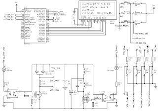
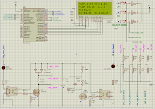
Circuit diagram of the microcontroller based two in one project of battery performance monitor or tester and desulphator is as below.
 |
| Circuit diagram of Microcontroller based battery internal resistance Monitor |
There are Four Segments of the schematic shown in above figure:
1. The Interface of Microcontroller with LCD
2. For adjustment of parameters, the provision of three input push button
3. The measurement of voltages at various stages of project during operation
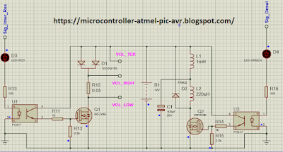
4. Power module of battery tester which is again consisting of two parts:
(a) The battery Tester side, which left side of power module section
(b) The desulfator power section which is at the right side of power module
These will be discuss one by one in detail in below sub-section of this post. Various components used in each section will be introduced and their functionality will be explained as under.
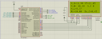
Microcontroller Project Schematic Part-1: 18f452 interfacing with 4-lines 20-Character LCD:
In the first part of whole schematic of this microcontroller project, we will discuss the interfacing of LCD with the PIC Microcontroller which is 18F452. The LCD we are using here in this battery tester cum desulphator is a large LCD which is consisting of Four Lines and each line will have twenty Character spacing. The various parameter will be display at different lines of LCD using microcontroller. The alpha-numeric LCD is interfacing using standard four line interface method as shown in the figure below:
Microcontroller interfacing LCD for Battery Tester Project
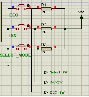
Microcontroller Project Schematic Part-2: 18f452 interfacing with Three Push Buttons:
Three push button have been provided to user for the adjustment of values of critical parameters to be adjusted according to the needs of user real time. These Push buttons are as under:
1. The Setting Selection Mode Switch
2. To increase the parameter values, the ICREMENT Button
3. To decrease the parameter values, the DECREMENT Button
The push switches are pull-up with 10kohm resistors and when press the logic zero is transmitted to microcontroller which is sensed during key-button scanning and the function is performed as per request of user of battery tester at that time, as shown in figure below:
 |
| Three push button with 18F452 PIC Microcontroller |
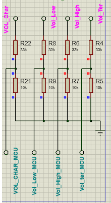
Microcontroller Project Schematic Part-3: Analog Voltages Measurement Interface to Microcontroller:
As the battery Attached for testing may have voltage 6V, or 12V, or 24V which are larger to be interface with microcontroller which accept voltage up to 5v. Therefore voltage divider is used as shown in the figure below: Two resistor are used one is 33Kohm and second is 10Kohm which divide the 12V divided by a factor of approximately 3.3 which is in acceptable range. If user have to interface larger battery the values of above resistor can be re-adjusted and factor used in program as well.
 |
| Voltage Divider Circuit Diagram |
Microcontroller Project Schematic Part-4: Power Module of Battery Tester and Battery Desulfator:
The N-Channel MOSFET Transistor , shunt resistor of 0.05Ohm, is used in Battery Tester side. Whereas The N-Channel MOSFET Transistor, two inductors, diode, capacitor is used in desulphator side of power module as shown in figure below. The battery is at the center of these two type of interfaces. It may be noted that only one function is performed at a time. It means that when we are measuring the internal resistance, the desulfator part is turned off. At an other time when the desulfation of battery is in progress the measurement of internal resistance is switched off. So that each function is performed independently without interference to each other. In this way the results are achieved perfectly.
 |
| Battery Tester CUM battery Desulfator |
Complete circuit diagram of the battery tester project:
 |
| Battery Tester Complete Schematic Circuit Diagram using PIC Microcontroller |
Programming of Battery Tester:
The program is written in PIC Basic Language and compile using proton basic compiler, the code listing is provided as under:
    Device = 18F452
    Declare Xtal = 4

    Config_Start
    OSC = HS         ' Oscillator Selection HS
    OSCS = Off       ' Osc. Switch Enable Disabled
    PWRT = On        ' Power-up Timer Enabled
    BOR = Off        ' Brown-out Reset Disabled
    BORV = 42        ' Brown-out Voltage 4.2v
    WDT = Off        ' Watchdog Timer Disabled
    WDTPS = 128      ' Watchdog Postscaler 1:128
    CCP2MUX = On     ' CCP2 MUX Enable (RC1)
    STVR = On       ' Stack Overflow Reset enabled
    LVP = Off        ' Low Voltage ICSP Disabled
    Debug = Off      ' Background Debugger Enable Disabled
    CP0 = Off        ' Code Protection Block 0 Disabled
    CP1 = Off        ' Code Protection Block 1 Disabled
    CP2 = Off        ' Code Protection Block 2 Disabled
    CP3 = Off        ' Code Protection Block 3 Disabled
    CPB = Off        ' Boot Block Code Protection Disabled
    CPD = Off        ' Data EEPROM Code Protection Disabled
    WRT0 = Off       ' Write Protection Block 0 Disabled
    WRT1 = Off       ' Write Protection Block 1Disabled
    WRT2 = Off       ' Write Protection Block 2 Disabled
    WRT3 = Off       ' Write Protection Block 3 Disabled
    WRTB = Off       ' Boot Block Write Protection Disabled
    WRTC = Off       ' Configuration Register Write Protection Disabled
    WRTD = Off       ' Data EEPROM Write Protection Disabled
    EBTR0 = Off      ' Table Read Protection Block 0 Disabled
    EBTR1 = Off      ' Table Read Protection Block 1 Disabled
    EBTR2 = Off      ' Table Read Protection Block 2 Disabled
    EBTR3 = Off      ' Table Read Protection Block 3 Disabled
    EBTRB = Off      ' Boot Block Table Read Protection Disabled
Config_End

    Declare LCD_DTPin = PORTD.4
    Declare LCD_ENPin = PORTD.2
    Declare LCD_RSPin = PORTD.3

    Declare LCD_Interface = 4               ' 4-bit Interface
    Declare LCD_Lines = 4                   ' 2-Line LCD
    Declare LCD_Type = 0                    ' Alphanumeric LCD type

    Symbol I_R = PORTC.3  'DEC_SWITCH

    Symbol B1 = PORTC.5 ' Select_MODE_Switch
    Symbol B2 = PORTC.6 ' INC_SWITCH
    Symbol B3 = PORTC.7  'DEC_SWITCH

    TRISD = %00000000  'All OUTPUT
    TRISC = %11110000  '// 0 t0 3 output and 4 to 7 input

    Declare Adin_Tad = FRC              ' Set clock source (x/FOSC or FRC)
    Declare Adin_Stime = 150            ' Set sampling time (in uS)
    Declare Adin_Res = 10
    ADCON1 = %10000000                  ' Set PORTA analog and right justify result
    Dim     Vol_Un_LOAD     As Word     ' Volatge at termminal without load
    Dim     Vol_Ter         As Word     ' 10-bit result of A/D conversion for Volatge at battery terminal
    Dim     Vol_High        As Word     ' 10-bit result of A/D conversion for Voltage at high side of shunt resistor
    Dim     Vol_Low         As Word     ' 10-bit result of A/D conversion For Voltage At low side of shunt resistor
    Dim     Vol_Charge      As Word     ' 10-bit result of A/D conversion For Voltage At charging side of shunt resistor
    Dim     R_inT           As Float    ' Internal Resistance measurement
    Dim     Dis_C           As Float     ' Discharge current
    'Dim     Char_C          As Float     ' charging Current
    'Dim     d               As Byte
    Dim     mode_op         As Byte      ' The two mode of functions are selected by this variable
    Dim     mode_0_count     As Byte     ' The times to function each paert of project
    Dim     secondary_cycle_count As Byte ' Time slice
    Dim duty_cycle          As Byte       ' PWM DUTY CYCLE valraible
    Dim cycle_count         As Byte       ' Program CYCLE are counted and displayed on LCD
    I_R = 0 ' Internal Resistance measuremtn Signal OFF
    ''''' INITIAL WELLCOME MESSAGE'''''''''
    Print At 1,1, "Wellcome..DeSulfator"
    Print At 2,1, " Battery Project"
    Print At 3,1, "microcontroller-atmel-"
    Print At 4,1, "pic-avr.blogspot.com"
    DelayMS 1000   ' One Second Time delay
    Cls        ' Clear The LCD DISPLAY
 ''' INITIALIZATION of LOCAL Variables
     mode_op = 0
     secondary_cycle_count = 0
     mode_0_count = 5
 ' for a PIC16F877,
 'Channel 1 is CCP1 which is pin PortC.2.
 'Channel 2 is CCP2 which is pin PortC.1.
' Start loop, reads temperature. Loop forever

'''''' Main program Starts here'''''''''''
    While 1 = 1

    If cycle_count < mode_0_count Then       '' The check the cycle for approprate functioning
    mode_op = 0
    Else
    mode_op = 1
    EndIf
    '''''Adjustment of testing time''''''
         If B2 = 0 Then Inc mode_0_count
         If B3 = 0 Then Dec mode_0_count
         If mode_0_count <=1 Then mode_0_count = 1
         If mode_0_count >=5 Then mode_0_count = 5
 ''''''' Select SWITCH CASE for execution of each function one by one'''''''
        Select mode_op

        Case 0
        ''''CASE 0 for the measurement of battery health by calculating the internal resistance
        Cls
        HPWM 2,0,8000  '' Turn OFF the PWM during measurement of internal resistance
       '''' The battery Voltages are being measured without any load'''''
        I_R = 0  '' MOSFET is OFF
        Vol_Un_LOAD = ADIn 0   ''' analog to digital conversion of un-load terminal voltage of battery
        DelayMS 100

        I_R = 1  '' MOSFET is ON
        Vol_Ter = ADIn 0  ' Analog to Digital Conversion of Terminal Voltages of battery with load
        DelayMS 10
        Vol_High = ADIn 1 ' Analog to Digital conversion of voltage at high side of shunt resistor
        DelayMS 10
        Vol_Low = ADIn 2  ' Analog to Digital conversion of voltage at low side of shunt resistor
        DelayMS 10
        I_R = 0    '' MOSFET is OFF
' The Internal resistance of battery will be calculated using following formula'''''
''''R_int =  shunt * (Unload_V - Terminal_V)/ (High_V - Low_V) '''''
        R_inT = 0.05 * (Vol_Un_LOAD - Vol_Ter) / (Vol_High - Vol_Low )
'''Current passed through the shunt resistor during load will be calculted using this'''
        Dis_C = R_inT * (Vol_Un_LOAD - Vol_Ter)
''' The results are displayed on LCD''''
        Print At 1,1, "V_U=", Dec2 Vol_Un_LOAD* 0.02101 ," VT=", Dec2 Vol_Ter* 0.02101
        Print At 2,1, "V_H= ", Dec2 Vol_High* 0.02101,"  S_C ", Dec cycle_count
        Print At 3,1, "V_L=", Dec2 Vol_Low* 0.02101
        Print At 4,1, "Ri=", Dec2 R_inT * 1000, "  Ds_C=", Dec2 Dis_C
        DelayMS 1000   ' wait for one second

      ''''The second function the desulfator starts in next case'''''
        Case 1

        I_R = 0   '' The MOSFET for iternal resistance load side must be OFF
        Cls   '' clear the display
        Print At 1,1, "mode = 2 "
        Print At 2,1, "desulfation started"
        Print At 3,1, "S-Cnt ", Dec cycle_count
        HPWM 2,duty_cycle,8000  '''' Generate PWM signal of 8kHz with 50% duty Cycle

        DelayMS 1000
        'If duty_cycle >=254 Then duty_cycle = 10
        Case Else
                 Cls
        EndSelect

        Inc cycle_count
        If cycle_count >= 254 Then  cycle_count = 0

    Wend
No comments:
Post a Comment
Please ask if you have any question regarding the programming of MCU, or have any problem in development of your electronics project. microcontroller51.blogspot.com