Introduction of heart rate monitoring sensor:
To
monitor the heart rate or pulse rate of any human body, a dedicated sensor is
required. The sensor is basically a device which convert the information of
blood flow in vain of body into electrical signal. The signal generated from
pulse rate sensor are then process further to interface with microcontroller or
microprocessor of Arduino board. Where the digital signal are analyzed and then
results are displayed using any convenient means of display like LED display or
using LCD display. Therefore we can say that the Pulse Sensor is a especially
designed device which is ready for plug and play to measure the heart rate with
help of any kind of microcontroller like AVR on Arduino board or Microchip PIC
or Atmel 8051 family. This sensor is used by electronics engineering students,
professional engineers, software engineers, embedded project developers to
easily include the live data of heart rate into projects. There are variety of
sensors available for this purpose. The pulse monitoring sensor are usually fixed
or attached with help of a clip onto a fingertip or sometimes it can be used on
earlobe to get the heart rate data from the body of human.
Principle of construction of Heart Rate Sensors:
The
important point of in the discussion regarding the construction of heart arte
sensor is that the technique used for the detection of pulse rate is non-invasive
type of detection or measurement. These sensors are consisting of optical
electrical devices. The majority of the optical heart rate sensor do have f an
electronic circuit built-in with them in addition to sensing element to proper shape
the electronics signal so that these could be easy interfaced with
microcontroller or any digital signal processing device. The operation of the
sensors starts with the monitoring of heart beat by clipping these onto a fingertip.
The working
principle involved in the working of the Heart beat Sensor is Photo-ple-thysmo-graph.
This principle in based to detect the changes in the volume of blood in apart
of body like finger. The volume of blood is measured by the variation in the
intensity of the light passing or blocked through that organ. The source of
light in a heart beat sensor is usually an IR LED and the detector may be of any
light intensity Detector like a Photo Diode, a Light Dependent Resistor (LDR)
or a Photo Transistor. These two parts work tighter to form an understandable
electronics signal.
Parts of pulse sensor:
Parts
of a typical pulse rate sensor are basically two;
1. IR
transmitter: The function of IR transmitter is to emit IR which will be used to
detect the blood in veins. Basically the media used for the detection of pulse
is Infra-Red Radiations.
2. IR receiver:
The function of the IR receiver is to collect the IR passes through the finger.
Some of the IR will be blocked when blood passes through the veins. The
difference in the intensity will be actually the determination of pulse.
Types of pulse sensor:
There are two techniques which are used for the detection
of heart beat;
1.
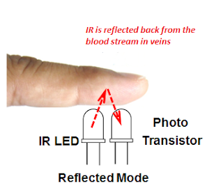
Reflection Based Detection of Heart Beat:
In this method the light or IR radiation is emitted from IR
transmitter and received by IR receiver or photo diode or photo transistor. The
light source (IR Transmitter) and the detector (Photo Transistor) are place at
same side of a finger or organ (adjacent to each other). The finger of the
person is placed in front of the transmitter and receiver. The light is reflected
through the finger and a portion of it is blocked and rest of the light passed
when blood sticks in veins. The light is shining on the finger and the part
reflected back to photo transistor is measured. The quantity of light varies
with the amount of blood in veins of finger. As the quantity of blood changes
significantly in corresponding the heart function continuously. As a result the
pulses are formed through the photo diode or photo transistor end.
 |
| Reflection Based Detection of Heart Beat |
2.
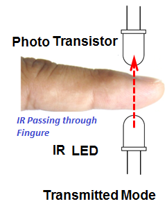
Transmission Based Detection of Heart Beat:
In this method the light or IR radiation is emitted from IR
transmitter and received by IR receiver or photo diode or photo transistor. The
light source (IR Transmitter) and the detector (Photo Transistor) are place
facing each other and the finger of the person is placed in between the
transmitter and receiver. The light is passed through the finger and a portion
of it is block when blood sticks in veins. The light is shined and passes
through the finger which is directly relates to the quantity of blood in vein
at that time. As we know that the quantity of blood always changes, as a result
we get pulse at the light collection device which is in our case the
photo-transistor or photo-diode. This is a continuous process of up and down as
a function of blood pumped into the finger.
 |
| Transmission Based Detection of Heart Beat |
Working of Heart beat Sensor with an electronics circuit # 1:
So far we have discussed the theory of working of a pulse
sensor. Now we should move to its particle used. In fact the pair of light
emitting device and light sensing device are not all the components to get the
desired output. We attach some of analog electronics components to make them
working. Here we will discuss the construction a simple circuit in which we
could be able to detect a pulse using above discussion about the sensor. Therefore
we can say that a typical Heart beat Sensor will be consisting of detection
based devices along with electronics circuit. The detection part of the Heart beat
Sensor will have an IR LED and a Photo Diode/ transistor placed in a clip. The electronics
circuit will be consisting of an Op-Amp along with a few other analog
electronics components like resistor & capacitors. This electronics circuit
will help us to connect the detection part of sensor to signal processing unit
like a Microcontroller. The working of the Heart Beat sensor is easily and
becomes more interesting when we do a detailed study of the circuit diagram.
 |
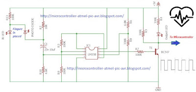
| Obtaining Electrical Signal from Heart Beat Sensor |
The circuit diagram shown in above figure is based on assumption that the clip sensor part or detection part is attached with the finger. When the heart beat sensor have finger in place between the detectors the pulses are started to detect. As we have already discussed that with every heart beat the amount of blood in the finger will change from minimum to maximum level in the vein. The light emitted from the IR LED on passing through the finger get interactions with the blood quantity. The amount of light managed to pass through the obstacle of blood will be thus detected by the Photo Diode. The amount of light will be the function of amount of blood in vein as a result a changing electrical signal will be available at the photo diode terminal which is then processed through the use of OP-AMP. Here we will use LM358 OP-AMP which is consisting of two op-amp inside a single ship. The output of the photo diode is feed to the non–inverting input of the first op–amp through a capacitor. The use of capacitor at this stage is to block the DC Components of the signal coming from the detection unit. The amplification factor of at this stage is kept around 1001. It is sufficient to amplify the week signal to a level which is desirable. The output of first non-inverting amplifier is feed to second op-amplifier which is built in a comparator mode. The output of second op-amplifier (Comparator0 is used to feed to a transistor to have train of pulses as shown in the circuit diagram above. It may be noted that the construction of this circuit is very simple and efforts are made to use the general purpose components which are easily available in local electronics market or on a radio shop. For example the use of op-amp LM358, the transistor could be any NPN like c828 or BC 547.
Working of Heart beat Sensor with an electronics circuit # 2:
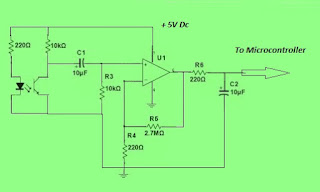
The above circuit has been built in order to have response from optical sensor used to monitor the heart rate pulses as discussed earlier. The only difference is that it is very simple circuit as compared to previous one but it has very good results too.
 |
| Interface of optical heart rate sensor |
In
this circuit we are using the IR transmitter coupled with the photo transistor.
Again it is the assumption that the finger is placed in between the optical
transmitter and optical receiver so that the light have obstacle with blood. For
the optical sensor assembly (U2), we used a reflective optical sensor. This
sensor has transistor output. Coming to the Op-Amp again we can use the LM358
or Lm 741 as per our convenient choice. But I think for the sake of experiments
the results of LM358 are good enough. It is to be noted that the light of the
LED is at the peak emitter wavelength 950 nm. The Designers or engineers
normally use a range between 700 nm (Red light) to 1000 nm (infrared light) for
biological instruments. The light beam have to cross the narrow parts of the
body like a fingertip or an earlobe or the lower lip therefore use of this
range of light is safe and workable.
No comments:
Post a Comment
Please ask if you have any question regarding the programming of MCU, or have any problem in development of your electronics project. microcontroller51.blogspot.com