Construction of Heart Beat Monitor using PIC Microcontroller:
The measurement Heart Rate is very important parameter of the human body which is related to cardiovascular system. As we know that the heart rate of a healthy young person is around 72 beats per minute (BPM). Some person like Athletes may have lower heart rates. The babies have higher heart rate around 120 bpm. The children may have heart rates around 90 bpm. Another fact is that heart rate rises gradually during exercises and returns slowly to the rest value after exercise. However, the monitoring is BPM is important to know if the heart is working perfectly in normal circumstances. Here we will design of a very low cost device which will measure the heart rate of the person by clipping sensors on one of the fingers and then displaying the result on a LCD. This project is based on microcontroller. The microcontroller is programmed in such a way that the heart rate meter will display various measurement results and their interpretation that the value is normal or not. The project can be programmed to display the average, maximum and minimum rates over a period of time and so on.
The project we are constructing in this post
will be consisting three main components like the sensor, processing unit, and
display. The Sensor of this project is consisting of an infrared transmitter
LED and an infrared sensor photo-transistor. The sensor for detection of proper
heart beat of a human is actually in the form of a pair of two semi-conductor
parts, transmitter & receiver. This sensor is mounted into a casing which
can be clipped on one of the fingers of the patient or whose BPM are required
to measure. The LED in the sensor described above will emit infrared light
which will be passed into the attached finger of the patient. The
photo-transistor of this sensor will detect the IR beam. The changes in the
intensity of light will be the function of changes in the volume of blood in
the finger. Thus, it will actually measure the change of blood volume in the
finger. The signal generated at the photo transistor end will be in the form of
pulses but in the order of mv means very low level. It requires proper
amplification. The signal from optical sensor attached to the finger of patient
is then amplified and process accordingly. The analog signal is then fed to PIC
microcontroller for counting of pulses, analysis and display. The
microcontroller used in this project is a very low cost simple PIC
microcontroller which is very easily available at local electronics parts
market everywhere. The number of the microcontroller is PIC 16F84. The MCU counts
the number of pulses for one minute. The
Pulses per minute are actually the Beats per minute or the heart rate of that
person. Three readings are taken consisting of each for one minute then the results
are averaged out and final averaged BPM are displayed. The calculated averaged heart rate is
displayed on an LCD in beats per minute.
Circuit diagram of Heart Beat Monitor using PIC 16F84
 |
| Circuit diagram of Heart Beat Monitor using PIC 16F84 |
The analog signal processing unit is an electronics circuit which is consisting of two operational amplifiers and a low-pass filter. The use of OP-AMP here is this circuit is required to amplify the weak signal from photo transistor to a level which is acceptable for microcontroller. As we know that the PIC microcontroller 16F84 will work on DC 5V power supply therefore, this MCU will operate its input/ output pins or ports at TTL level. Thus OP-AMP section of this project is designed so that the pulse shall obey the TTL rules for proper counting at microcontroller stage. Now again back to the operational amplifier circuit designing, here we will like to tell that the first operational amplifier is used to amplify the signal with a gain of about 100. The second operational amplifier will further amplify the signal and give it proper shape with the gain around 560. While performing the testing of this circuitry at designing stage it was realized that a low pass filter shall be included in the operational amplifier stage circuit to filter out all unwanted high frequency noises coming from nearby equipment or instruments etc. The cut off frequency of this filter was selected as about 2Hz. A red color LED is also connected at the output stage of the operational amplifiers which flashes as the pulses are generated or passed from this circuitry to the microcontroller section. The output of the operational amplifier & low pass filter circuit is fed to one of the digital inputs of a PIC16F84 microcontroller. The microcontroller is operated from a 4MHz crystal. The microcontroller output ports drive the LCD. When the Heart Beat Monitor is powered ON by applying the power supply to it. The Welcome message is display on LCD after that instruction to operate appears on LCD.
Sequence of operation of Heart Beat Monitor using PIC 16F84 Microcontroller
 |
| Various Display Screen during Measurement |
Press start
button to get the reading. Here the user has to press the start button. Immediately
after that the microcontroller will start counting the pulse for obtaining the
reading # 1 and at that time LCD display will show calculating 1. Here one
important thing shall be noted that the sensor shall be applied to patient
before the pressing of start button. After completing the first measurement
time, the unit will continue counting for second measurement and display on LCD
will be changed from Calculating 1 to calculating 2. After the completion of
required time period for this measurement, the display will be changed to
calculating 3. When the heart rate monitor unit have successfully measured the
three reading, then it will perform averaging and the averaged results will be
display on the LCD. If it in normal range, message will display “NORNAL”. If the
averaged value is at lower side, or higher side the message will be display
accordingly. The reset button is required to press for re-using it again.
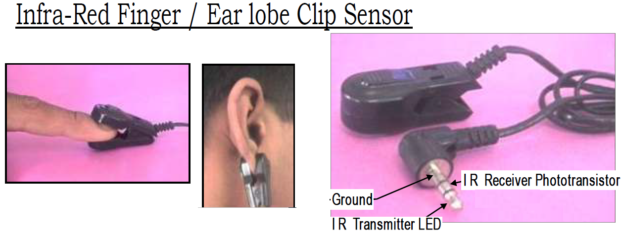 |
| Optical Sensor used in Project of Heart Beat Monitor |
Some
important facts about the sensor are: These sensor clips consist of only a pair
of IR photo transistor and receiver LEDs enclosed in a specially designed
plastic clip housing and cable with stereo jack plug. The probe clip alone does
not have any other circuit. To use the probe, you must have some suitable
application circuit or compatible pulse rate monitor. For the best results the
application environment should be away from direct sunlight or high intensity
lights and the person under observation should stop any body movements /
exercises.
This project can further be improved in coming post covering it in the field like use of a graphical LCD. Sound effects can be included to the meter like a sound is produced each time a pulse is received at microcontroller. Similarly, the maximum & minimum values of heart rates during the measurement can be displayed. For the sake of data logging onto personnel computer or laptop, the Serial communication can be added to this project.
The Warning
or abnormalities in the case of very high or very low heart rates are displayed
on the LCD with the indication by an LED and a buzzer.
'* In this project a PIC16F84A microcontroller is
'* used and an infrared sensor is connected to pin
'* RB0. Also, a button is connected to pin RB1 of
'* the microcontroller.
'* The average heart rate is measured and
'* displayed on a LCD
'*****************************************************
Device = 16F84A ' selection of device = Microcontroller

Xtal = 4 ' the crystal frequency

Symbol SVIC = PORTB.1 ' decaration of input/ output PIN of MCU
Symbol PIN  = PORTA.1
Symbol BLK  = PORTA.0
' decaration of local variables
Dim Cnt As Byte
Dim Heart As Word
Dim J As Byte
Dim B As Byte
TRISB = %00000011

Cls' clear the display
DelayMS 1000 ' wait for one minute
' prints the welcome message
' prints the instruction for start
Print At 1,1, "     READY...   "
Print At 2,1, "  PRESS  START  "
'
' Wait until BUTTON pressed
'

While SVIC = 1:Wend  ' waiting for button to press

Cls ' clear the screen
Heart = 0 ' initialization of HB parameter

For J = 1 To 3
    Print " CALCULATING ",Dec J
    Cnt = Counter PORTB.0,10000
    Cnt = 6 * Cnt
    Heart = Heart + Cnt
Cls
Next J

Heart = Heart / 3 ' averaging
Cls
' Warning section
If Heart<=40 Then
GoTo WARN1
ElseIf Heart>=100 Then
GoTo WARN2
Else
    Print At 1,1, "NORMAL HEARTRATE"
    Print At 2,1, "Heart = ",Dec Heart," /min"
    Sound PIN, [25, 50]
    DelayMS 250
EndIf
GoTo FIN

WARN1:
    Print At 1,1, " LOW HEART RATE"
    Print At 2,1, "Heart = ",Dec Heart," /min"
GoTo BEEP

WARN2:
    Print At 1,1, "HIGH HEART RATE"
    Print At 2,1, "Heart = ",Dec Heart," /min"
GoTo BEEP

BEEP: ' produces sound
For B = 1 To 3
    Sound PIN, [25, 50]
    DelayMS 250
Next B

ABN: ' blinking of LED
    High BLK
    DelayMS 200
    Low  BLK
    DelayMS 200
GoTo ABN

FIN:
    End    ' end of program
FAQ about Heart Beat Monitor
What does the microcontroller-based heart rate monitor do using fingertip sensors?
The
heart rate monitor is a metering device used to measure the heart beats. Its construction
involve the use of microcontroller inside it. The device which actual measure or
detect the heart pulse is attached to the finger of a person, thus this monitor
has a fingertip sensor with it.
Is this device is using the heart rate app free download for android?
Currently
this heart rate monitor is constructed so that it will work stand alone.
However, in future we have a project in which will be using android for
measuring the heart beat and its app will also be developed accordingly.
how does a heart rate monitor work?
The
heart rate monitor work with the use of an optical sensor attached on the
finger of a person to detect the pulse of heart and the value is displayed on
LCD or LED display of the monitor.
Is this similar to the heart rate sensor apple watch?
The
function of this heart rate monitor is also to detect and display the heart
pulses, but the apple watch for heart rate sensor has some additional feature
like to communicate with iPad, iPhone etc.
Is this monitor using Arduino heart rate sensor?
No,
our heart rate monitor uses the optical sensor, it does not use the heart rate
sensor based on Arduino or other. However, we have used PIC Microcontroller in
it for data processing and display purposes. Arduino does similar jobs. As we
know that Arduino boards also uses microcontroller but those are made up of
Atmel AVR.
Is it the finger clip heart rate monitor?
Yes,
it is the finger clip heart rate monitor, whose sensor can be attached to finger
of a patient or to the ear of patient.
Is this project like heart rate monitor for android smartphone?
This
project we have developed so far uses PIC Microcontroller in it. It does not
use the android smartphone. However, we are planning to develop a heart rate
monitor using android smart phone in future, on its completion, it will be
posted here on this blog.
Does it support the Arduino heart rate sensor code?
No,
our heart rate monitor does not support the code written for Arduino. The code
written for this heart rate monitor is in basic language and compiled using proton
plus compile.
Is it the heart rate monitor with LCD?
Yes,
an alpha numeric LCD of 2lines has been attached with this heart beat Monitor.
Where is the heart rate sensor schematic?
The
schematic circuit diagram is provided and explained above.
What is the use of potentiometer in heart rate monitor?
The
potentiometer in heart rate monitor are used in the analog signal processing
area, where the operational amplifier are configured using resistors and
capacitors to have desired amplification gain and signal level, so that the
signal can be feed to microcontroller for the measurement of heart pulses.
How will we be understanding heart rate monitor readings?
It
is very simple the results will be shown on LCD in the form of BPM.
In which language the code for heart rate monitor is written?
The
Basic language is used to write the program of heart rate monitor and the
proton plus complier is used to convert basic language code to hex file.
how to analyze an electronic heart pulse readout
The
normal range is defined in the program code listing, if the readings are not in
normal range of heart beat, then appropriate warning message is display on LCD.
Keyword research: The heart rate monitor circuit diagram is provided above. The heart rate monitor experiment is done and results are very encouraging. This heart rate monitor is without chest strap. This heart beat meter is similar to the analog heart rate monitor sensor (ecg) for Arduino but different in a sense use of different microcontroller. The sensor of this monitor can be applied to the ear also.


