Showing posts with label Project Proposals. Show all posts

Solar Tracking System Microcontroller PIC 18F452

Solar Energy Tracking System using microcontroller

Abstract of Solar Tracking System:

The goal of the project is to develop and implement a solar energy tracking system using a microcontroller. To find out alternative sources of energy and get maximum efficiency from such non-conventional energy source is the need of present and future. This project involves around the requirement that how we can design an efficient solar panel system to acquire maximum solar energy from it. This is the reason we are try to design this project.

Introduction of Efficient Solar Penal System:

As the energy costs are increasing with the decreasing supplies of conventional fuels, the need arises to find out sustainable alternative forms of power. These energy source shall be such that to protect the environment from the harmful releases of gases. The Solar energy is one of the big sources which is being implemented. The Solar panels are usually fixed at certain angle, although a reasonable amount of energy is produced from these panels. But production of electricity can even be increase with the use of an intelligent solar panel tracking system which control the direction solar electrical panel in a way to face the sun at the maximum time. If we design a system which control the solar electrical panels such that it always faces the sun, then we will be able to get maximum advantage from sun light with the use of existing solar panels.  This microcontroller project involves a solar tracking system which is designed with a microcontroller, optical sensors and motors. The position of sun and panel is checked and best suitable direction is calculated then the panels are moved in such direction that panel should face the sun exactly. The position or directional angle with respect earth of the Sun is not fixed. Therefore the angle at which sunlight strikes the earth surface also varies through the day. Therefore the solar panel will have variable amount of light whole the day. The production of electrical energy will also be not constant. So the direction of solar panel need readjustment through the day in order to have sun facing angle, so that maximum light may fall on solar panels. All this happening due to the rotation of the Earth around the sun in our sun solar system. The Solar-electrical panels shall absorb sunlight maximum to give maximum electrical energy. It can only be achieved if the solar-electrical panels are incessantly moved and placed inline with direction of the Sun to have maximum sunlight all the time. Therefore the solar-electrical panel will be constantly subject to adjustment-readjustment rotational angle as a function of direction of Sun. This microcontroller project is designed to obtain the desired goal for having maximum efficiency from existing solar-electrical system with applying tracking algorithm.

Solar Panel for Maximum Electrical Energy Tracking System Objectives:

The main objective of the project is to design a solar tracking system using pic microcontroller. However besides this we will achieves some associated advantages like we will be able to learn about the working of the solar energy panels tracking system, implementation of a microcontroller from PIC family to achieve the target, the needs of a solar energy tracking system, the appropriate methods of tracking the solar energy generating panels used, the design methodology and constraints in the development of efficient solar panel tracking system, the designing of schematic circuit diagram of tracking system using microcontroller from the PIC family, writing the software and code listing for the PIC microcontroller in the construction of an efficient solar panel electrical tracking system.

The Philosophy of Solar tracking system:

The solar energy converting electrical panels tracking system works with on an idea to get the maximum energy from the existing solar to electrical panels with implementation of a smart electronics controller with the solar panels. It is already in understanding that the solar panels are installed at the roof of the house or any other building with the intension to get the electrical power from the light and heat of the sun energy with the help of these solar-to-electrical panels. It is worth mentioned that the solar-electrical panels convert solar energy into electrical energy with an effective implantation of photovoltaic principle. It is very obvious that the intensity of light from the sun plays the important role in the production of electrical energy from the panels, more electrical power with higher intensity of light.  Is there any other factor which can serve to obtain more electrical power from the solar-electrical panels? Yes the direction of placement of panels is much important, the panel shall be placed in a suitable direction that maximum light from sun can fall directly on the panels. This project is designed for the controlling the position and direction of solar-electrical panel in such a way that the light from the sun fall directly on panels and maximum energy may be converted and obtained. Therefore here we will be developing a controller of panels to rotate them accordingly with the hanging the position of sun.

By using this tracking system, we will be able to expose solar panel for the maximum time in front of sunlight and thus we will be able to get the maximum power from the existing solar panels. There are two well pronounced methods which are used for the Solar tracking system. These are the Sun-Solar tracking system and Time-Solar tracking system. These two methods are briefly explain below.

Time solar tracking system:

The information of time and season is additionally gathered from the database to find out the exact direction where the sun light is maximum. In this method time plays an important rule to decode the rotation of earth around the sun. The use of real time clock in the control circuitry of solar tracking system with microcontroller will do the purpose. As the season give different angles of direction where sunlight is more than usual. Therefore the tow parameters together will decide it.

Sun Solar tracking system:

The solar tracking system, as its name indicates that it will track the sun. The solar panels rotated with the help of motors in the direction of sun. As the quantity of light changes with the rotation of earth around the sun, therefore it is necessary to measure the intensity of light. The Light dependent resistor (LDR) or photo diode are used for this purpose. The electrical signal generated by optical sensor is processed and command to motors is issued in response. As a result the solar panels gain the direction where the light is maximum.

The optical sensors which will be either the LDR or the photo diode or photo transistor will measure the intensity of light. There are two optical sensors used which are separated by an insulator of light, so that each may work independently. Initially both sensors are calibrated when same amount of light is given to each of them. After their installment at the panels, now the light intensity from each of optical sensor is measured using the microcontroller. In ideal conditions when same amount of light falls on both sensor, they should give same amount of electrical output and the motor shall not move in any direction unless one of the sensor start giving less or grater light. With the start of day, the output of sensors will not balance each other therefore microcontroller will generate command to motors to bring the panels in the direction of sun, where the light is maximum and both optical sensor read equal amount of light. Following are test cases of project:

Case # 1: When the electrical signal from both sensor is same, reflecting that the intensity of light is same at both optical sensors. In this case the solar-electrical panels will be assumed that the direction is perfect and there is no need to rotate in any direction. Solar panel will remain in this position.

Case # 2: When the output of the optical sensor is not equal. The optical sensor # 1, which is on left side of panel reads more intensity than the sensor # 2 which is at right side of the solar panel. It will happened usually in the morning time, left optical light sensor will be on higher intensity. Then solar panel will start rotating will the help of stepper motor to left direction where the two sensors get same reading of intensity. It will be the point where maximum solar light will fall on the solar panel and out optimum direction.

Case # 3: When the output of the optical sensor is not equal. The optical sensor # 2, which is on right side of panel reads more intensity than the sensor # 1 which is at left side of the solar panel. It will happened normally afternoon, when the right side optical light sensor will be on higher intensity as compared to the left side optical sensor. Then solar panel will start rotating will the help of stepper motor to right direction till the two sensors have same response. Then we get our desire direction where maximum solar light will fall on the solar panel.

The 2-D solar tracking System:

The Solar energy is also called free source of energy that’s why it has gain more popularity as compared to other renewable energy resources. Moreover the emission of burned fossil fuel bi-products and hydrocarbon which are destroy our environment are not associated with the power generation from the solar system. The Solar-electrical named as Photovoltaic (PV) panels are the devices which convert the sun light into electricity energy. Once a solar system is planned to installed anywhere for the generation electricity from sunlight, then the point of concern come that the maximizing electrical shall be acquired to increase the efficiency of solar system at the available resources. To achieve this goal the solar or photovoltaic panels must be kept aligned with the direction of sunlight through the use of a tracking system which will focus on the direction of the sun.

 Usually the fixed type PV panels don’t follow the sun direction that’s why their efficiency overall remain at lower side. On the other hand the sun tracker which work on single axis principle, the solar panel are adjusted and re-adjusted in East-West direction. The solar tracking system which work on the principle of two-axis tracking  have more precise adjustment of direction of solar panel by moving the panel into two direction. The up -down and left – right movement of solar panel in order to have maximum output will increase the efficiency even more. Thus a solar tracking system consisting of two axis tracking using microcontroller will be more efficient.

It is learnt that the efficiency of PV panels is a function of various parameters like environmental temperature, humidity, rain, status of cloud and dust level on panels. This project is a Microcontroller based two axis Solar Tracking system which adjust the direction of solar panel so that the efficiency of solar panel is increased considerably.

Components used in the development of general purpose one axis solar tracking system.

If we wish to develop a low cost general purpose one dimensional solar tracking system then we will have to build a few components like Solar panel, PIC18F452 microcontroller, Optical sensor based on Photo Transistors or photo diode, A set of resistor, Servo Motor, 8MHz Crystal, 22pF Ceramic Capacitors, Connecting Wires, Stepper motor, ULN2003, Oscillator, Resistors, Capacitors etc.

Construction of Two Axises Solar Tracking System:

On the implementation of the tracking system, we will be considering the direction of the sun which will be varying in two directions up-down and left-right. The horizontal direction from the observer to the sun is called the azimuth angle. Whereas the vertical direction from the observer to the sun is called altitude angle.

Schematic Circuit diagram of the Two-Axis Solar Panel Tracking system using microcontroller PIC 18F452:

The Schematic Circuit diagram for double axis solar tracking system has been designed, prepared and analyzed in Proteus ISIS software. The full circuit of 2-D solar panel tracking system is shown in Figure # 1. 

Complete Circuit diagram of 2-D Solar Tracking System
Figure # 1: Complete Circuit diagram of 2-D Solar Tracking System


The whole schematic circuit diagram of the project is consisting of following main sections:

1.     The central processing Unit Board CPU consisting of PIC Microcontroller 18F452

2.     The Sensor Boards consisting of Temperature sensor LM35 and optical sensor LDR.

3.     The Keyboard consisting of four push switches and a latched button.

4.     The LCD based display Unit Board

5.     The Motors controller boards

6.     The LED status board

7.     The power supply section

     The details of component and construction of each section and its board is discussed as below. The functionality of whole project will be explored step by step as under.

Solar Tracking System Central processing Unit Board (CPU)

For the processing of information gathered from the sensors and obtaining the useful results for the effective control of DC motors, the CPU boards is designed, as shown in the diagram (Figure # 2) below. 

Microcontroller PIC18F458 Connection with circuit diagram of solar Tracking system
Figure # 2: Microcontroller PIC18F458 Connection with circuit diagram of solar Tracking system

The tasks done under this brain board of the solar tracking system developed using Microcontroller are listed as under:

1.    Measuring the signal from the optical sensors (04 Nos). The four optical sensors (LDR) are required to mount on each side of solar panel i.e to detect the light intensity at Upper side, lower side, right side and left side. The Light intensity signal is processed by converting the analog voltage level to digital by using built-in ADCs of the Microcontroller. The digital number corresponding to light intensity levels at each side are formatted properly to be utilized effectively in the logic decision section of program.

2.  Measuring the analog signal from Temperature sensors (QTY: 04 Nos). The four Temperature sensors (The Integrated Analog Temperature Sensors LM35) are required to be mounted on each side of solar panel i.e to detect the Temperature at Upper side, lower side, right side and left side. The analog signal from LM 35 is processed by converting the analog voltage level to digital by using built-in ADCs of the Microcontroller. The digital number corresponding to the degree of Temperature at each side are formatted properly to be utilized effectively in the logic decision section of program.

3.  The sensing to keyboard which is consisting four directional keys i.e. up-ward, down-ward, left and right side keys. These keys are used to the manual motion of solar panel (if required).

4.    The scanning of a logical latched button which used for the selection of Logical decision, whether the decision should be based on results of Temperature sensors or optical sensors, or otherwise the logical decision will be based on results of Temperature sensors and optical sensors. This selection is very important in decision matrix. Because there will be location where we will be preferring to utilized the optical sensors as input only for the implementation of proper direction of solar panel. In this case the temperature reading will be ignored in making the decision of motion. In other condition we will preferably utilized the results from both type of sensors and if logic from both sensors is in same sense, then motor will be operated accordingly to adjust the direction of solar panel.

5.  Updating the LCD display with the current measured values of the four temperature sensors and four LDR, the optical sensors at the LCD. The user will have to look if he wants to know what are the temperature and light intensity levels at various sides of the solar panel. Is the controller is working perfectly or algorithm shall be modified.

6.    The issuance of movement commands for each motor separately when required for the adjustment of solar panel UP-DOWN (Vertical Movement) direction and Left-right direction (Horizontal Movement). There are two motors which are responsible for the 2D axis adjustment of the solar panel in right direction and angle.

7. The main program will be performing the calculations and producing the proper commands for motor control (if required). It will be discussed in more details in the Logical decision making section.

The components used in the CPU boards, the brain and heart of the solar tracking system, which is the main processing board and act as the essential electronics board of project are listed as below:

1.    The PIC Microcontroller 18F452. It is selected for three reason that the ADCs results of this microcontroller are stable. Secondly, the number of IO lines required for this project meets by using the PIC 18F452 Microcontroller. Third reason for the selection of this microcontroller is that it has sufficient RAM, ROM to support the software requirements of this solar tracking system.

2.  Crystal 8 MHz: The 8 MHz crystal is very optimum choice, how ever the project can easily work on the 20MHz crystal as well. There is any number in between 8 and 20 MHz crystal will efficiently work.

3.     Capacitor 33pF (QTY: 02 Nos)

4.     Resistor 10k Ohm

5.     Capacitor 104 mounted on power supply lines. Although it is not shown in the schematic diagram, but is sued because the Power supply are not visible or shown in circuit diagram prepared in the software Proteus ISIS.

6.  Capacitor 100uF 16V mounted on power supply lines. Although it is shown in the apparent circuit diagram, but it is recommended to be used in parallel with the power supply lines to have a good filter power supply to microcontroller.

Sensor Boards:

There are four sensor boards used in the project of solar tracking system using microcontroller PIC 18f452. Each board has one temperature sensor and one Optical sensor as shown in figure # 3. The temperature sensor we are using in project is an integrated analog temperature sensor LM35 which is good for general purpose applications and its response is also acceptable. It gives analog output signal 10mV/degree C. The optical sensor is LDR, whose resistance varies with the intensity of light. When light strikes on the LDR sensor, then the resistance of the photo sensor decreases. It means that during day time its resistance will be low in the order of a few hundred Ohms (400 to 500 Ohms) and in night its resistance will be high in the order of a few kilo Ohms (1400 to 1500 Ohms). In the day time its resistance will be function of amount of light falling on it in the range of say 150 Ohm to 700 Ohms. Thus potential difference across the LDR will be direct presentation of the intensity of light. If there is less light strike on it, its resistance will be high and voltage drop across it will be lower and vice versa. The two analog signals from each board are feed to the ADC (Analog PINS) of the Microcontroller PIC 18F452. Where the analog signal is then converted to digital signal and processed accordingly.


Placement of sensor at solar panel for sun tracking system using Microcontroller PIC18F452
Figure # 3: Placement of sensor at solar panel for sun tracking system using Microcontroller PIC18F452

Keyboard

A small keyboard consisting of four push buttons and latches button is designed and attached with the microcontroller board to accept the input from users. The reason of this keyboard is to facilitate the user of solar tracking system to give manual commands to microcontroller for the proper fixing of location or direction of solar panel. The circuit diagram of the keyboard is presented in figure # 4 as below.

It is consisting of simple push button which are pull-up with 10kOhm resistor for the generation of proper logical signal. When any of the key is press, a corresponding logic “0” is obtained otherwise due to pull-up resistors the logic “1” will be on each switch output line. The four push button corresponds to provision of input for movement in four direction like up, down, left or right direction of solar panel for the fine adjustment if required by user.

Key Board Interfacing Circuit diagram with Microcontroller for Solar tracking System
Figure # 4: Key Board Interfacing Circuit diagram with Microcontroller for Solar tracking System


One latch switch or button is provided at keyboard front panel for the selection user intension for logical decision regarding the direction of panel. The facility is provided to use optical sensor input with logical or with temperature input. At the other position of switch, it will logical and the inputs of the temperature sensor and optical sensor. Thus in this selection case, the decision will consider the input from both sensors, if it is coincide then movement command will be generated.

LCD based display Unit Board

An LCD of four line and twenty characters is used for the display of the current temperature and intensity levels on the screen front panel. The LCD is interfaced with microcontroller using four bit mode. The total six IOs lines of Microcontroller are used for the data and command communication between LCD and microcontroller as shown in figure # 5 below. Four IOs lines are for data and two IOs lines for control line to give LCD enable signal, and RS signal to LCD. The LCD is used in fixed write mode. The contrast of LCD is controlled using a potentiometer, variable resistor, of 10kOhm. The LCD will work on DC 5V power supply which will be shred from microcontroller board power supply section.
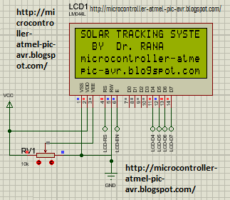
LCD Display Connection with circuit diagram for solar tracking System
Figure # 5: LCD Display Connection with circuit diagram for solar tracking System


Motors controller boards

There are two DC Motors required to be used in this project of solar tracking system using microcontroller PIC 18F452. Therefore there are two motor control board designed to control one DC motor by each motor controller board. Each Motor control board I consisting of four transistors, two PNP and two NPN transistors. The Four transistors are configured to make the well know H Bridge type control of DC motor as shown in figure # 6 below. The PNP transistors are responsible for the provision of positive power supply connection to motor one terminal. On the other hand the NPN transistors are responsible for the provision of ground level voltage to the other terminal of the DC motor. As we know that the PNP transistor is active or start conduction when operated as switch on the availability of logic “0” on its base terminal. Whereas the NPN transistor when configured in switch configuration will be active on the provision of logic “1” at its base. One PNP and one NPN transistor share one IO line. Therefore at a time only one transistor will be active. Thus for the effective control the direction of motion of DC motor, two control IOs of microcontroller are used. At idle time, both IOS will have same logic level. But for motion in particular direction i.e. clockwise or anticlockwise, the logic level on one IO line will be high whereas logic level on the second IO line will be low. Therefore at this time one PNP and one NPN transistor from opposite in diagonal when conduct, as result one terminal of DC motor will receive positive supply and other end of motor will receive ground level. Then the motor will start rotating till the change of status of IO lines. The Four PN junction protection diode are also used in the motor controller board to nullify the reverse emf generation problem of DC motor. These diode are for the safety of transistor because otherwise transistor may burn out on the generation of reverse emf at the terminal of motor.

MOTOR DIRVE CONTROL Circuit diagram of Solar Panel Tracking System
Figure # 6: MOTOR DIRVE CONTROL Circuit diagram of Solar Panel Tracking System


It may be noted that the specific number of PNP and NPN transistor and diodes are not being mentioned with the intension that the user may select the components to meet the requirement of load, DC motor specifications etc. Therefore the power supply of DC motor will also be appropriately selected on the basic of requirement of DC motor.

LED status board

A board is designed to show the movement of solar penal if any motor is operated at any time with the help of four LEDs which corresponded to the movement of direction in four side. The same IOs lines used for the control of direction of rotation of motor used by motor controller boards are used here to glow the respective LED with the utilization of TTL IC, 7408 and 7404, AND gate logic IC and NOT gate logic IC respective as shown in the figure # 7 below.

LED Status Board for Motor Motion Indication
Figure # 7: LED Status Board for Motor Motion Indication


Power Supply Section

Apparently the microcontroller and associated boards works with regulated DC 05V power supply which is consisting of a step down transformer, rectified diodes, filter capacitor and an analog voltage regulator LM7805 IC. As the overall current consumption of the circuits is not high and remains in the range of about 100mAs to 150mAs. Therefore use of LM7805 IC is enough which is usually cable to provide 1000mAs regulated power supply. However the DC motors selected for this prototype project works on DC12V and may draw current in the range of 1Amp. Therefore a spate power supply for the motors will be required to match the requirement of motors. As we are not fixing the selection of motor at this stage therefore the user or developer is responsible for the section of appropriate DC motors and their power supply along with the proper selection of PNP & NPN transistor pairs in the motor controller board. This end is kept open and component can be selected based on the actual requirements.

Software of the 2-D solar Tracking System Using Microcontroller PIC 18F452:

The program coding of the 2-D solar tracking system is written and compiled using Proton Plus Basic Complier for PIC Microcontroller. Its code listing is provided in the next post. Please visit the Post " Program for Solar Tracking System".

The other microcontroller based degree projects and many hobby projects of Microcontroller are available here.

ROBOTICS PROJECT IDEAS FOR ENGINEERS USING MICROCONTROLLER

 Mechatronics Engineering Students Degree Projects Robotics and Microcontrollers

Robotics Introductions

The modern world will be functioning on robots. All the activities being performed by human will be switched to perform by robots. Everywhere will be automation. It is evident by the increase of automation everywhere around us. There are good number of people who support the use of robotics in automation. With the robotics, the complex tasks can be done easier with higher precision as whereas the same done by human are subject to the human errors. Robotics is a field which is emerging more and more. The robotics as profession is taken with passion to learn and to solve different problems in the environments where are human cannot perform jobs. There are various fields involve in the robotics to complete the task done by robots like programming, electronics, mechanics, automation, and computer science etc. Therefore we can say that the filed Robotics, itself is a multidisciplinary field based on suitable combination of fields and engineers belonging to mechanical, electrical and computer science. To do final year degree projects of electrical engineering, mechanical engineering or computer engineering or electronics engineering in the field of robotics the project ideas are presented below to help the student of engineering universities.

1.     The Automatic Cleaning Robot

The robot used for the cleaning of any special area are designed in such a way that the robot shall perform the cleaning task efficiently. It is normally done by use of some marking or boundaries where we are going to deploy a robot for say cleaning task. The automatic cleaning of an area or a room will be done using microcontroller based a robot which will identify the area using borders with IR technology. The robot will be allowed to follow any path to cover the entire room, it may be straight or zigzag, but the condition is that it shall remain with that area. The sensors in this robot could be optionally the ultrasonic or IR. The robot system will carry a vacuum cleaner attached to it. The dust will be collected in a bin attached to the vacuum cleaner. Besides the main task of cleaning there would be some decoration task of the system like to display the time of utilization and area that it cover to interpret the efficiency of the robot application. The microcontroller used in this project will be programmed to follow the set rules and display the parameters on a LCD attached at the front panel to give specific information to user.

2.     Robotic Vehicle to Pick and Place Things

In industry the automation is key to have maximum production. The robot are helping industry in variety of applications. One of the important development in the robotic field is the development of a robot which is used to pick and place things in a specific order. This type of robot are usually designed custom based, focusing the need of industry where these are required to deploy. The specially designed robot will provide the services for the movement of object in any of desire direction and arises like horizontal or vertical, and rotational. Similarly robot can be made to provide rotational as well as linear movement. The number of arms of robot are also flexible choice. The student can take this project to develop a 2D or 3D movement robot with two or three arms. The development of robot of such types will be a challenging task for engineering student focusing the available resources. 


3.     Robot for the carrying object and climbing at stairs in harsh environment

The Use of Robots to transport objects or goods in harsh environment is a challenging task, especially when the transportation is to be performed in off road like on stairs. There will be some complex mechanical design required for application like this. The student of mechatronics engineer can more focus on this project. The route of transportation will have to be feed in the memory of robot and it will be edited every time the root has to be changed for alternatively a compunction protocol shall be adopted. The GPS system will also be an integral part of this application. The robot will be capable enough for climbing over obstacles and can climbing the stairs. This application will be suitable in a harsh environment where the human are not easy to perform this task due to multiple reason like because of high temperature or incomputable chemical environment. 

4.     Control of Robotic vehicle with help of Touch Screen

The robotic vehicle are often used for various tasks. The wheels, motors, microcontrollers or Arduino are used to make a robotic vehicle. There are some input devices are attached to provide command and control to the robotic vehicles. In this project, it is proposed to attach a touch screen with other electronics components like microcontroller, microprocessors, ARM or Arduino to get input from touch screen and execute the commands accordingly. There would be many ways to establish communication channel with the main CPU of robot and the touch screen which will includes the use of RF technology if we have to control the robot from a small distance or RS-232 serial communication, or Bluetooth communication, or even WIFI can be used for this purpose. Thus there are many variation which can be worked to design a robotics project innovatively. 

5.     Robot to Follow Line of Trajectory

The robot which flow a path through the scanning of a line trajectory is called a line follower robot. The thick line is drawn on the floor or other suitable surface. The robot detect the line by using sensor based on infrared (IR) or other optical devices. The line tracing is done real time during the execution of motion command to robot. There are two motors with wheels attached to the rear and a castor wheels of robot to support it for necessary movements. The development of a robot which is capable to flow a line trajectory path is a nice robotic projects for the final year engineering students. The microcontroller used in such a robot is 8051 sufficient because there are no complex calculation involve n these robots. They are design just to flow the track. The straight line is not necessarily required, you can give any complex path to robot depends upon the resolution of detection. 

6.     Solar panel Cleaner Robot

The use and deployment of solar plates for the generation of electric energy is increasing day by day. There is always need to keep the solar panel plates clear to required level as much as possible in order to have maximum efficiency of solar plates for maximum generation of electricity from the solar system. For small and medium scale solar system, the cleaning of solar system can be done manually, however for the large scale solar systems, the cleaning of these plates required some automatic robotic development. To clean such a solar system plates, a robot can be very helpful. A robot to help in the cleaning large area spaces can be developed using appropriate microcontroller and battery backups. The engineering students can make this kind of robot for their degree project by using the RF technology in the robot to send movement commands for controlling the direction of motion with specific tools.

7.     Robot to Play Chess

Play chess is a fantastic indoor game all over the world. Now what a nice idea it would be if the robots are playing the chess instead of human. The development of this intelligent robot will be consisting of best approaches in the field of robotics and computer vision for the chess by robot. The code will be written in Python for Raspberry Pi in which the implementation of camera is incorporated. The robot will takes images using the installed camera in order to visual recognize the placement of objects on the floor of chess. The movement of object will be detected by the comparing the images. The robot will use Stockfish which is a chess engine. The use of this chess engine will be essential to recognize the moves of second player and to decide the move of the robot to make.  

8.     Robotic for Vehicle having Metal Detector 

The fabrication of Robotic for Vehicle having Metal Detector involves the use of two types of main systems, one for the control of motion of a vehicle and to the detection of metal. This project can be developed as whole or in parts or in two phases. Some students can have one ready to use system and deploy it on the second system. The metal detection system can be constructed by using 8051 family microcontroller to achieve the control of vehicle. The motion of vehicle can be control by applying the necessary command through the use of any suitable media like remote control, like Wi-Fi or Bluetooth devices. The motor will be used to assist the robot for any specific motion. The use of pushbuttons to send commands for forward, backward, left, and right motion will be required. When a command will be received at the robot by media like RF technology, the command will be interpreted by microcontroller 8051 which will further issue the commands to motors for required motion in the asked direction. The metal detection system will be optionally developed or purchased a ready to use and will be attached to the vehicle to detect the metal around the robot. There will be buzzer or other notification arrangements attached to the robot to give signal on successful detection of metal by the robot. 

9.     Mobile Robot

The robot which is capable to detect the things or obstacles of different nature and change the path accordingly will be a good choice for engineering student to develop as a degree project. The objects found in the path of robot will be detected with help of optical sensor and intelligently robot will change its path real time. The robotic system will be made by using some powerful microcontroller like Raspberry Pi. There is another optional task which can be associated with this robot is to capture the images and store these images on suitable storing media for analyses on later stage. Therefore it is proposed that this system may incorporate a USB camera with the robot which should be capable to interface with a Raspberry Pi. 

Bread Board Circuit Connection of Robotic Project


10.   Robot to Print 3D Objects

The 3D printing of objects with help of use of robots is an idea to make degree project. It may involve the use of mechanical parts, electronics analog and digital components, Computer or mobile interface, and Microcontroller or Arduino board.  The design at computer or mobile or laptop will be read by microcontroller or Arduino and will be processed and then appropriate commands to run or move the stepper motors and attached arms will be executed using coordinates system. Then the printing will be started with the effective control of ink or laser printing head. The project can be utilized in the industry of textile, or can be used in the industry where the labels of various projects are designed and printed on actual media. The scope of utilization of this three D robotic printing is very vast. Student can do this for the completion of thesis and can do further research to make innovating design. 

Bidirectional Production line Counter using ATMEGA8 Microcontroller

Display unit of  Industrial Production Line Counter

Synopsis of Microcontroller project for the Final year Student of Engineering

In this Microcontroller Experiment we will learn to develop an Automatic Production Line counter Using Microcontroller and We will design the circuit diagram along with the writing of software for the effective implementation of the Automatic production line counting system and display of counter at dominant place in the factory for its effective use.

Scope of Project:

This project is related to the design of an automatic production line counting system for the product counter in an industrial environment. This project will be helpful for the students of Electronics, Software, and Mechatronics field of engineer to develop this project for their final year degree project.

Introduction of Microcontroller Degree Project

A counting system for the products during the production from an industrial machine is always of greater concern for the management point of view. Therefore the counter and display of production line is required to design. Here we will make the schematic circuit designing and software coding for the development of automatic event counter. The use of Microcontroller make the counting of product more efficiently, the other main components to be used in the project will be like sensor which are based on optoelectronic switch associated electronics component like resistor, capacitors and digital Integrated Circuits (ICs). There is provision of Data acquisition so that a Personnel Computer (PC) could be interfaced with the counting system to get the data into the PC through the use of RS-232 serial communication Protocol. The Software on PC will be capable enough to register the actual quantity of the Production line, event date & time and planning efficiency for future production rate etc. The experimental use of this automatic event counting or production line counting will prove its credibility with the advantages like reliability, easiness in operation and accurate results. It is worth mentioned that this system has many application and uses in real world like its usability starting from the home appliance to large scale industrial manufacturing factories states. Some of the usage of this system are elaborated as it can be used as Meter-age Counter for the counting of length of cloth production textile industry, Folding Machine Counter, Jigger Programmer for the counting of length of cloth in dying machine and several round of that cloth in dying tube, each time it is required to measure the length of cloth very accurately by giving it desirable Temperature and tension and many more,  Weaving Length Counter, Shift Production Counter, Dosing Controller or dozing counter are also the requirement of industry and counter are widely used for it, Production Data Monitor,  Deca & Doff counter, cloth Length measurement system, Inspection Machine Counter, Speed Indicator, Shrinkage Monitor, Warping Length Counter, Loom Production Meter,  Yarn Length Counter, Spinning Automations, etc. Industrial production lines products final product from raw materials and their counting is done by the use of appropriate counter. To keep all record up-to-date about the above said production lines is really a job. In an industry many processes will be running simultaneously. Thus automatic counters are a big need of industry. Therefore above counters are frequently used in various places.

Construction of Microcontroller based Automatic Counter and display System:

This counting and display system uses Microcontroller Atmega with optical sensors to ensure the forward and reverse counting through the effectively use of electronic circuitry with them. The Microcontroller optical Sensor, LED seven segment display, suitable power supply, necessary electronics components will be mounted on a PCB board to develop. The LED display will work on the famous technique of multiplexing the digits which will be describes later in this post. The system will work as a fully automated industrial production line counting system. The optical sensor will transmit and receive light signals to detect product or things which are required to count. When an object will crosses the sensor path, then a response will be generated by sensor indicating an object. This technique will ensure that all objects are being counted.

Direction base Counting of Objects:

When the object start moving in front of the optical sensors, the pulses will be generated and these will be counted using the systems attached with it. Similarly when any machine moves then the optical sensors attached with the shaft will continue to produces the pulses on making and breaking of the light between the sensor elements. What if one wants to know in which direction the shaft is rotating, clockwise or anticlockwise direction because the direction of rotation is important in any industrial applications.  As the counting of pulse does not serve the purpose all the time. Like, if it is desired that counter may increment with one direction of rotation and decrement with the reverse direction of rotation. In these situation one have to use an up & down counter with proper circuit to identify the direction of rotation.

Direction of rotation detection


Redesigning of Counter for Direction Information:

So let’s redesign the existing simple pulse counter to a special up & down counter with help of a very simple circuit. There will be two optical sensor pair will be used instead of one pair of LED and receiver. So that we have two pulses one after another. These pair of pulses will be feed to a D-type flip-flop integrated IC like TTL IC 74LS74. The 74LS74 will sense the sequence of occurring of these pulse and will distinguish that which pulse come first among pulse “A” or Pulse “B”. The direction will be identified using the D-type flip-flop 74LS74 like is it clockwise or anti-clock wise rotation. So the counter will increment the count or decrement the count as per the direction of rotation. This type of motion detection along with direction of motion detection is required in many applications likes in the field of robotics, in the control of various arms of CNC machine, and similarly in many applications involving the bidirectional mechanical motion.

The D-Type Flip Flop 74LS74

It is an integrated IC having two D-type flip flops, these flip flops are here used to identify the direction of rotation of the encoder. As we have already told that the two pairs of optical sensors will produces to set of pulses name “A” and “B”.  These pulses will be feed to the flip flops as per configuration shown in the schematic circuit diagram below. As a result, we will be obtained two pulses labeled clock wise and anti-clockwise. If the encoder will rotate clock wise the pulses will be available on clockwise pulse train only. If the encoder will rotate anti-clockwise direction then the pulse will be available on the anticlockwise train. Each is feed to external interrupts of microcontroller.

Counting of Pulses:

The external interrupts of Atmega8 Microcontroller are configured as activate on the fallen edge. If the pulses come on clockwise pulse train then interrupt number 1, be activated and increment in counts will be resulted. If the encoder will rotate counter-clockwise direction then anti-clock-wise pulse train will generate pulse and the second external interrupt of microcontroller will be activated which will decrement the counts.

Schematic Circuit diagram of the Project:

ATmega8 Microcontroller based Bidirectional Counter


Multiplexed Seven Segment Display:

The display of the project is a four-digit common cathode type LED seven segment display. The Seven segment display is configured in the multiplexing way. The digit will glow one by one. Thus, is done in the software.

By using the technique of multiplexing, the control of display using seven segments to displays the production count becomes very simple. The main advantage of use of this technique is that it requires a smaller number of IO pins of microcontroller as compared to conventionally attaching all pins of seven segment display to the microcontroller which seems not easy with small microcontroller. It will require either an IO expander or a microcontroller having larger set of IOs. As we are using a small microcontroller of AVR named atmega8, which have limited number of IOs, thus we used the multiplexing technique of display number on the four seven segment digits. Therefore, the number of pins used to drive the displays are a few only. In the way the segments are driven high by the micro-controller turn by turn. First we turn one the transistor attached to first decimal place and at that time the code for digit is send to PORTB of microcontroller, as a results first digit place glows with that digit. At that time all other transistors are kept off, means all three remaining seven segment display digit will be OFF. After a delay of about 500 milli second, then the turn comes for second digit place and so on.

Microcontroller Atmega8:

In this project the AVR Microcontroller Atmegaa8 is used. The AVR Microcontroller ATmega8 is a low-power CMOS 8-bit microcontroller. It is based on the AVR RISC architecture. The ATmega8 has inbuilt ADC : the analog to digital converter, the built-in  internal oscillator and the serial data communication, performs the instructions in a single execution cycle. The ATMEGA8 has 1Kbyte Internal SRAM, 8 Kb of Flash program memory and 512 Bytes of EEPROM. The ATMEGA8 has three ports, port-B, port-C, and port-D. There are total 23 IOs line are available on these ports. There are two External Interrupt lines which are configured at port D. There are three-Internal Timers. This microcontroller is very efficient for small and medium size projects. The working of microcontroller is very stable. The performance of the microcontroller is excellent.

Software of Bidirectional Counter:

The software of the Bi-directional counter is written in BESCOM, basic language and compiler for the AVR microcontroller. The program code listing is provided at the end of the post.

Reset counting Button:

A push button is also interfaced with the atmega8 Microcontroller to reset the counting at any time.

'*****************************************
'Bi-Directional Production Line Counter
'*****************************************
$regfile = "m8def.dat"
$crystal = 8000000
$prog &HFF , &HE1 , &HD9 , &H00
On Int0 Downcount
On Int1 Upcount
Enable Int0
Enable Int1
Config Int0 = Falling
Config Int1 = Falling
Enable Interrupts
'*****************************************
' outputs  of the Microcntroller Atmega8
'*****************************************
Config Portb.0 = Output : Portb.0 = 0
Config Portb.1 = Output : Portb.1 = 0
Config Portb.2 = Output : Portb.2 = 0
Config Portb.3 = Output : Portb.3 = 0
Config Portb.4 = Output : Portb.4 = 0
Config Portb.5 = Output : Portb.5 = 0
Config Portb.6 = Output : Portb.6 = 0
Config Portb.7 = Output : Portb.7 = 0
Config Portc.0 = Output : Portc.0 = 1
Config Portc.1 = Output : Portc.1 = 1
Config Portc.2 = Output : Portc.2 = 1
Config Portc.3 = Output : Portc.3 = 1
'******************************************
'inputs of the Microcntroller Atmega8
'******************************************
Config Portd.2 = Input : Portd.2 = 1
Config Portd.3 = Input : Portd.3 = 1
Config Portd.7 = Input : Portd.7 = 1
'******************************************
'data for 7 segments
' Codes for common Cathode Type
' Seven Segment Display
'******************************************
Dim Digit(10) As Byte
' Dibit 0
Digit(1) = &B00111111
' Dibit 1
Digit(2) = &B00000110
' Dibit 2
Digit(3) = &B01011011
' Dibit 3
Digit(4) = &B01001111
' Dibit 4
Digit(5) = &B01100110
' Dibit 5
Digit(6) = &B01101101
' Dibit 6
Digit(7) = &B01111101
' Dibit 7
Digit(8) = &B00000111
' Dibit 8
Digit(9) = &B01111111
' Dibit 9
Digit(10) = &B01101111
'*******************************************
'veriables
'*******************************************
Dim Product_count As Integer
Dim Digit_place(4) As Byte
Dim I As Byte
Dim K As Integer
Product_count = 0
Portc.0 = 0 : Portc.1 = 0 : Portc.2 = 0 : Portc.3 = 0
Main:
'**********************************************
' 7seven segment display
'Conversion of the count to digit values
'**********************************************
I = Product_count Mod 10
Digit_place(1) = Digit(i + 1)
K = Product_count / 10

I = K Mod 10
Digit_place(2) = Digit(i + 1)
K = K / 10

I = K Mod 10
Digit_place(3) = Digit(i + 1)
K = K / 10

I = K Mod 10
Digit_place(4) = Digit(i + 1)
K = k / 10
'*********************************************
'Multiplexing the four digits
' Multiplexing seven segment display
'*********************************************
Portb = Digit_place(4)
Portc.0 = 1 : Portc.1 = 0 : Portc.2 = 0 : Portc.3 = 0
Waitus 500
Portc.0 = 0 : Portc.1 = 0 : Portc.2 = 0 : Portc.3 = 0
Portb = Digit_place(3)
Portc.0 = 0 : Portc.1 = 1 : Portc.2 = 0 : Portc.3 = 0
Waitus 500
Portc.0 = 0 : Portc.1 = 0 : Portc.2 = 0 : Portc.3 = 0
Portb = Digit_place(2)
Portc.0 = 0 : Portc.1 = 0 : Portc.2 = 1 : Portc.3 = 0
Waitus 500
Portc.0 = 0 : Portc.1 = 0 : Portc.2 = 0 : Portc.3 = 0
Portb = Digit_place(1)
Portc.0 = 0 : Portc.1 = 0 : Portc.2 = 0 : Portc.3 = 1
Waitus 500
Portc.0 = 0 : Portc.1 = 0 : Portc.2 = 0 : Portc.3 = 0
If Portd.7 = 0 Then Product_count = 0
Goto Main
'****************************************************
Downcount:
If Product_count = 0 then Product_count = 9999
Decr Product_count
Return
'****************************************************
Upcount:
If Product_count = 9999 Then Product_count = 0
 Incr Product_count
 Return

Popular Post (All Time)