Rotatory Shaft Encoder Speed-o-Meter

 Synopsis of 8051 Microcontroller Project For Speed Measurement:

The speedo-Meter will measure the speed of motor attached to an industrial production machine is being developed in this microcontroller experimental project. The application of this speed measurement project is comprised of a variety of field like it can be used in the home appliance to the production industrial machinery. In this 8051 Microcontroller project we will be doing to design a digital meter used as measuring device to be develop for measuring instantaneous rotational speed of the encoded shaft. The basic technique behind the measurement of speed to use a suitable incremental optical encoding-based algorithm. The sensor used to detect the motion of the shaft attached with the motor will be based on a custom-built optical encoder consisting of transmitter and receiver. Accurate real-time calculations for speed measurement will be performed in an Atmel AT89C51 microcontroller. The output will be shown on LED seven segment display in the form of Rotation Per Second (RPMs). The system’s functionality and implementation details are presented in the sections below.

Subject Descriptors:

  • Speedometers
  • Optical Encoding
  • Microcontrollers
  • Optical Encoder

Implementation of Software and Hardware for the development of speed measuring device:

Hardware will be based on the Atmel AT89C51 microcontroller, and the software will be written in Keil C51 Compiler and Micro vision IDE.

Introduction of the Final Year Degree Project based on 8051 MCU:

 The Speed measuring devices called speedometers of various types are often witnessed in automobiles, aircraft, traffic highways and industries - measuring and displaying linear and/or rotational speeds. These devices are basically classified and available as analog and digital meters (with respect to their output) and typically use mechanical, optical and acoustic means for their construction thus providing different degrees of accuracy. However, the basic objective behind using a speedometer is to control speed. Optical Encoding is a scheme that is commonly employed in a number of currently used digital speedometers, mostly for measuring rotational speed. This project is a prototype speed measuring system based on the technique afore-mentioned. Its function is to measure and display the rotational speed of a shaft. It provides a mechanical interface to input the rotary motion from external sources. The measured speed is displayed in the form of digits and is updated frequently following any change in the input motion. 

Scope of Project:

In current configuration, the system can measure only the rotational speed up to a few thousand RPMs (revolutions per minute) with a fine degree of accuracy using the number of microseconds elapsed as the time interval.

 Objectives

  •  To make it a lower-cost system as compared to other available such systems.
  • To provide a higher degree of accuracy than its counterparts.

 Significance and Common Applications

Optical Encoding base rotary speedometers can commonly be used as feedback devices for motor controllers.

  • They can also be utilized:
  • To provide visual feedback.
  • To increase compliance with traffic laws (e.g. on highways to check vehicle speeds).
  • For conducting speed studies.

Salient features Of Speed Measurement System

 Use of Optical Encoding:

Besides having low cost, fine accuracy and almost no parts to break, the Optical Encoding scheme is quite simple, flexible and easy to implement. Moreover, as the role of embedded digital systems and computers is getting more and more significant with time in every technological domain, digital interfacing capability has also become a mandatory feature in modern systems such as data acquisition systems, control systems etc. Using Optical Encoding scheme is the simplest way to incorporate such features into an application. 

 This project utilizes the same scheme to achieve the following goals.

  1. Lower Cost – Only a transmitter (infrared LED) and a receiver (phototransistor) are needed for the basic operation. Also there’s no wear and tear of components which ensures that no re-calibrations etc. are required.
  2. Better accuracy – Due to its fast response, less number of components required, discrete signal operation (digital output), no maintenance or calibration requirements, the Optical Encoding makes it easier to provide very accurate result over a high range of operation. 
  3. No Analog to Digital Conversion: Because of no analog to digital conversion involved, the system unsurprisingly has a number of significant plus points. 
  4. Finer accuracy – Analog to digital converters provide unique output value up to a certain number limited by the umber of output bits, which is a hardware dependency. E.g. a 12 bit ADC can provide only 2^12 (=4096) different speed values. On the other hand, this Digital Speedometer system performs its calculations using 32-bit software arithmetic operations, based on the revolutions per number of microseconds elapsed, which is far more accurate than a system using ADC. 
  5. Smaller time delays – The use of extra hardware components/stages introduces extra time delays, which is not desirable in any real-time application. Less hardware – Using lesser hardware than software is becoming a trend because it results in more flexibility, lesser design and debugging time hence more simplified overall design.

 Custom-Built Encoder Device:

 Instead of using commercially available Optical Rotary Encoders, there is a custom-made (built-from-the-scratch) device used in this project. The idea was simply to reduce the cost because their price in market ranges from $50, $70 to around $300.

 Use of 8051 based microcontroller device:

 The advantages in using a microcontroller are:

It allows one to move the whole logic and functionality in software, which is easily modifiable.  A number of development and debugging tools are available for this series of devices. Hence, the overall development time is reduced and a more reliable product results in.

 Architecture of the Speed-o-Meter

The speed measuring system based on microcontroller 8051 family has been divided in to following three subsystems:

  • Input scanning subsystem
  • Speed Measurement and calculation Subsystem
  • Display Control Subsystem

Detailed explanation of each of the above sub-system follows in the next section. The high-level architecture of the system is represented in Figure No. 1, below.


Block Diagram Of Speed Measurement System


Functionality and Implementation

This section explains the function of each of the subsystem in detail with its implementation and related issues step wise.  The Atmel AT89C51 microcontroller (Intel 8051 derivative) is used in this project to implement the speed measurement and display control due to its low cost, simple architecture, re-programmability and good development tools available.

Input Subsystem (ENCODER):

Converts the mechanical rotary motion into digital electronic pulses, which are input to the speed measurement subsystem. The frequency of these pulses is directly proportional to rotational speed of the external source. The shaft encoder being sued in this project is a sensor associated with the detection of mechanical motion. 
Encoder with optical sensor
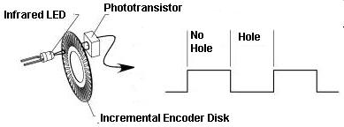
The encoders are used to translate the physical or mechanical motion such as speed, direction, and shaft angle into suitable electrical signals in the form of pulses. These pulses are detected and interpreted in rest of the circuitry to acquire the final results. The incremental encoder is an encoder to convert the mechanical motion to electrical signal which is made up of two main parts namely the disk having some dots or holes and the optical sensor. It is normal practice that the disk of an incremental encoder is patterned with lines on disk. The quantality of lines in a specific pattern on the disk is a function of the encoder resolution.it means that the encoder resolution will be higher if the lines are more closed to each other and the quantity of lines is higher per unit the length. The incremental encoders produce outputs related to the speed, angle and direction of the shaft. Similarly, the rotary encoder sensor also uses the light to detect the speed, angle and direction of a rotary shaft attached to some moving part of a machine. the linear encoder observes the linear strip to provide the required information for linear motion like speed, direction of rotation, revolution per unit time etc. On the other hand, the Optical encoders are built to use light signal to detect position, therefore theses are inherently free from close contact wear. Most optical encoders are transmissive type. The collimated light consisting of parallel rays passes through the disk and detected on the other side of disk. The pattern is detected using a sensor and which converts the light beam signal into TTL digital outputs. Physically, the input subsystem is an assembly (shown in Fig. 2) consisting of: 

  • A Metal Encoder Disk having a shaft for external mechanical interface and 4 equidistant holes along its circumference.
  • An Infrared Emitting Diode [Device ID: F5E2]
  • A Hermetic Silicon Phototransistor [Device ID: L14G3]

As the disk rotates, the light from the diode to the transistor is blocked and passed continuously. Due to this, the output of the circuit is low when the light passes through the disk hole and is high when the light is blocked. This produces digital pulses (0V Low, +5V High), which are fed directly into INT0 pin of the microcontroller. The advantage of using optical encoder becomes evident here, as there’s no voltage level conversion circuitry required. 

Speed Measurement Subsystem:

It’s the software existing in the microcontroller, which calculates the instantaneous rotational speed in real-time. The calculated speed depends upon the frequency of pulses received at INT0 pin. The speed is calculated in following manner. On each high (+5V) to low (0V) transition detected at INT0 pin by the microcontroller, an event (interrupt) is triggered in the software. The speed is calculated at this event using [Speed = Distance/Time] formula. The distance is a fixed known parameter (1/4 rotation for 4 holes in the disk) and the time taken is provided by the internal timer of microcontroller in microseconds. The interrupts may occur at higher rates up to 40, 50 per second with speed values being calculated at the same rate. As these real-time values cannot be displayed at the same rate, some display control mechanism is necessary which updates the speed display at a rate suitable for human eye. There is a possibility that the wheel is moving very slowly and no event is triggered up to a particular time. A maximum interrupt waiting time has been adjusted after which the speed is taken as zero. Being in software, this parameter can be easily set to any practically desirable value (e.g. 1 sec to 30 sec).

 Selection of an optimal Speed Measurement Technique:

  •  Two alternate approaches were available for calculation of speed.
  • Count the number of interrupts per unit time.
  • Calculate the time elapsed between two successive interrupts.

The second approach is far more accurate than the other because of its resolution in microseconds.

Design Parameters:

MAX RPM

Maximum No. Of Interrupts per second


For 1 Hole

4 holes

8 holes

20,000

333

1333

2667

10,000

167

667

1334

MIN RPM

Maximum Wait Time (sec)


For 1 Hole

4 holes

8 holes

10

6

1.5

.75

1

60

15

7.5

 Display Control Subsystem:

Displays the instantaneous speed in RPMs (revolutions per minute). Updates the display at a rate suitable for human eye. Typically, a 1 sec update time is desirable and practical; i.e. a speed value is shown on the display for a minimum of 1 sec. As the speed is measured at the interrupt arrival rate, a number of speeds values may have been calculated within display update time. In this case, the most recent value is displayed as it best fulfils the definition of instantaneous speed.

Seven-segment display:

In current system configuration, a common anode seven-segment digit display is used for output. In order to use least possible hardware, there’s a slight trick involved here. The seven lines (N’s of diode) of each LED are connected to the 7 pins of port P1 of the microcontroller. As the 7 lines of each LED are common, each digit is updated one by one very frequently, which makes the display look stable. A separate transistor for each digit is used for switching.

Circuit Diagram of Speed Meter:


Circuit Diagram of Speed Meter using Microcontroller 8051

Work Breakdown Structure (WBS)

The work Breakdown structure of this project may involve the sub-tasks like, Formulation of Problem Statement Initial Study Objectives Definition Selection of the Optimal Solution Subsystems Design Circuit Design Selected Optical Technique Understanding the AT89C51 Architecture and Assembly Language Learning C51 Software Implementation Simulation and Testing Circuit Implementation and Testing Hardware and Software Integration Testing and Verification Implemented on Vero Board Bringing into a Demonstrable Form.

Summary:

The Digital Speedometer is an incremental optical encoder based real-time rotational speed measuring system having low cost, higher accuracy and practical operating ranges. Using this system, one can observe accurate instantaneous rotational speed of an object.

Limitations:

  •  Currently only rotational speed is measured.
  • Minimum measurable speed is limited by the maximum wait time. The wait time is in the software can be adjusted up to an adequate value.
  • Maximum measurable speed is limited by the oscillator speed (in microcontroller) and the number of holes in the encoder disk.

Future Enhancements:

  • Linear Speed, Velocity, Acceleration can be displayed on multiple display devices.
  • Direction of rotation can be detected by using the quadrature technique with two diode/transistor pairs.

Reference Microcontroller Books consulted during the development of speed measuring system

Title: “The 8051 microcontroller”, 3rd edition

Author: I. Scott. Mackenzie

Software coding:

The software of the microcontroller project based on MCU At89s51 is written in C-Language and compiled on Keil C51 compiler. The code listing is presented as below:

//The Software of Speed Meter
// To include the library file related to Microcontroller
//At89S51
#include <AT89X51.H>
// Initialization and declaration of some variable to be 
// used in rest of program
int digit1=0,digit2=0,digit3=0;
// An array is taken to stort the codes
// for the seven segment display
int seven_segment[]={64, 124, 18,24,44,9,1,92,0,8};

#define MAX_WAIT_TIME_uSECS 2000000 

#define DISPLAY_UPDATE_TIME_uSECS 2000000 

#define MAX_TIMER_DELAY_uSECS 65536

#define TIMER_DELAY_uSECS 50000

#define TIMER_DELAY_VALUE  (MAX_TIMER_DELAY_uSECS - TIMER_DELAY_uSECS)

#define TIMER_INIT_VALUE TIMER_DELAY_VALUE

#define MAX_OVERFLOWS (20) 

#define UPDATE_OVERFLOWS (21)


void ext0isr();

void timer0isr();

void startTimer0();

void my_delay(int usec, int iterations);

void mydivide();	// tmplong / elpsedTime //


int maxwait_timerOverflowCount=0;

int update_timerOverflowCount=0;

int temp=0;

int rpm=0;

long elapsedTime=15000000+1;

long tmpq;

int quotient;


void main()
{		

	EX0=1;			//Enable external INT0
	IT0=1;			//External 0 edge triggered		

	TMOD = 0x11;	//Timer 0 16-bit mode	

	ET0=1;			//Enable Timer0 interrupts

	startTimer0();

	EA=1;			//Enable all interrupts

	while(1)
	{					
			P3_3=0;
			P1=seven_segment[digit1];
			P3_5=1;
			my_delay(100,1);
			P3_5=0;
			P1=seven_segment[digit2];
			P3_4=1;
			my_delay(100,1);
			P3_4=0;
			P1=seven_segment[digit3];
			P3_3=1;
			my_delay(100,1);		
	}
}


void int0_ISR() interrupt 0
{
	TR0 = 0;	//Stop Timer; to read value//
	
	// Read current elapsed microseconds //
	elapsedTime = TH0;
	elapsedTime <<= 8;
	elapsedTime |= TL0;

	elapsedTime -= TIMER_INIT_VALUE;

	// Add microsecond due to overflows occured//
	elapsedTime += 
	maxwait_timerOverflowCount * TIMER_DELAY_uSECS;

	//Calculated factor. Dirty !!//
	elapsedTime += 25310;

	// Now we have the complete elapsed time //

//	mydivide();	
//Divides the distance by elapsedTime. Only calculates the quotient//

//	rpm = quotient;


	// Calculate RPM ; Multiply numerator by 1E6 to make it seconds //
	//rpm = 60 * ROT_PER_INT * 1.0E6 / elapsedTime;
//	rpm = 15000000 / elapsedTime;	
			
	// Reset time //
	maxwait_timerOverflowCount = 0;

	startTimer0();

}	


void timer0_ISR() interrupt 1
{		
	TR0 = 0;
		
	++maxwait_timerOverflowCount;
	++update_timerOverflowCount;

	// If Maximum-wait-time has elapsed; Set RPM to zero //
	if(maxwait_timerOverflowCount == MAX_OVERFLOWS)
	{
		maxwait_timerOverflowCount=0;
		elapsedTime=15000000+1;
	}


	// If update time has arrived //
	if(update_timerOverflowCount == UPDATE_OVERFLOWS)
	{		
		mydivide();	
//Divides the distance by elapsedTime. Only calculates the quotient//
	
		temp = quotient;	// RPM is in quotient //
		
		digit1 = temp%10;
		temp/=10;
		digit2 = temp%10;
		temp/=10;
		digit3=temp%10;

		update_timerOverflowCount = 0;
	}


	startTimer0();

}


void startTimer0()
{
	TR0 = 0; // Stop Timer //

	//Load high byte for timer delay into TH0 //
	temp = (TIMER_DELAY_VALUE & 0xFF00)>>8 ;
	TH0 = temp;

	//Load low byte for timer delay into TL0 //
	temp = (TIMER_DELAY_VALUE & 0x00FF);
	TL0 = temp;

	TR0 = 1;		

}


void my_delay(int usec, int iterations)
{
int temp;
usec=-usec;
	while(iterations>0)
	{
		temp=usec & 0xFF00;
		temp>>=8;
		TH1=temp;
		temp=usec & 0x00FF;
		TL1=temp;
		TR1=1;	
		while(!TF1);
		TR1=0;
		TF1=0;
		iterations--;
	}
}


void mydivide()
{
	quotient = 0;

	tmpq = 15000000;

	while(tmpq > elapsedTime)
	{	
		tmpq -= elapsedTime;
		quotient++;
	}
	//tmpq has the remainder//	
}


Bidirectional Production line Counter using ATMEGA8 Microcontroller

Display unit of  Industrial Production Line Counter

Synopsis of Microcontroller project for the Final year Student of Engineering

In this Microcontroller Experiment we will learn to develop an Automatic Production Line counter Using Microcontroller and We will design the circuit diagram along with the writing of software for the effective implementation of the Automatic production line counting system and display of counter at dominant place in the factory for its effective use.

Scope of Project:

This project is related to the design of an automatic production line counting system for the product counter in an industrial environment. This project will be helpful for the students of Electronics, Software, and Mechatronics field of engineer to develop this project for their final year degree project.

Introduction of Microcontroller Degree Project

A counting system for the products during the production from an industrial machine is always of greater concern for the management point of view. Therefore the counter and display of production line is required to design. Here we will make the schematic circuit designing and software coding for the development of automatic event counter. The use of Microcontroller make the counting of product more efficiently, the other main components to be used in the project will be like sensor which are based on optoelectronic switch associated electronics component like resistor, capacitors and digital Integrated Circuits (ICs). There is provision of Data acquisition so that a Personnel Computer (PC) could be interfaced with the counting system to get the data into the PC through the use of RS-232 serial communication Protocol. The Software on PC will be capable enough to register the actual quantity of the Production line, event date & time and planning efficiency for future production rate etc. The experimental use of this automatic event counting or production line counting will prove its credibility with the advantages like reliability, easiness in operation and accurate results. It is worth mentioned that this system has many application and uses in real world like its usability starting from the home appliance to large scale industrial manufacturing factories states. Some of the usage of this system are elaborated as it can be used as Meter-age Counter for the counting of length of cloth production textile industry, Folding Machine Counter, Jigger Programmer for the counting of length of cloth in dying machine and several round of that cloth in dying tube, each time it is required to measure the length of cloth very accurately by giving it desirable Temperature and tension and many more,  Weaving Length Counter, Shift Production Counter, Dosing Controller or dozing counter are also the requirement of industry and counter are widely used for it, Production Data Monitor,  Deca & Doff counter, cloth Length measurement system, Inspection Machine Counter, Speed Indicator, Shrinkage Monitor, Warping Length Counter, Loom Production Meter,  Yarn Length Counter, Spinning Automations, etc. Industrial production lines products final product from raw materials and their counting is done by the use of appropriate counter. To keep all record up-to-date about the above said production lines is really a job. In an industry many processes will be running simultaneously. Thus automatic counters are a big need of industry. Therefore above counters are frequently used in various places.

Construction of Microcontroller based Automatic Counter and display System:

This counting and display system uses Microcontroller Atmega with optical sensors to ensure the forward and reverse counting through the effectively use of electronic circuitry with them. The Microcontroller optical Sensor, LED seven segment display, suitable power supply, necessary electronics components will be mounted on a PCB board to develop. The LED display will work on the famous technique of multiplexing the digits which will be describes later in this post. The system will work as a fully automated industrial production line counting system. The optical sensor will transmit and receive light signals to detect product or things which are required to count. When an object will crosses the sensor path, then a response will be generated by sensor indicating an object. This technique will ensure that all objects are being counted.

Direction base Counting of Objects:

When the object start moving in front of the optical sensors, the pulses will be generated and these will be counted using the systems attached with it. Similarly when any machine moves then the optical sensors attached with the shaft will continue to produces the pulses on making and breaking of the light between the sensor elements. What if one wants to know in which direction the shaft is rotating, clockwise or anticlockwise direction because the direction of rotation is important in any industrial applications.  As the counting of pulse does not serve the purpose all the time. Like, if it is desired that counter may increment with one direction of rotation and decrement with the reverse direction of rotation. In these situation one have to use an up & down counter with proper circuit to identify the direction of rotation.

Direction of rotation detection


Redesigning of Counter for Direction Information:

So let’s redesign the existing simple pulse counter to a special up & down counter with help of a very simple circuit. There will be two optical sensor pair will be used instead of one pair of LED and receiver. So that we have two pulses one after another. These pair of pulses will be feed to a D-type flip-flop integrated IC like TTL IC 74LS74. The 74LS74 will sense the sequence of occurring of these pulse and will distinguish that which pulse come first among pulse “A” or Pulse “B”. The direction will be identified using the D-type flip-flop 74LS74 like is it clockwise or anti-clock wise rotation. So the counter will increment the count or decrement the count as per the direction of rotation. This type of motion detection along with direction of motion detection is required in many applications likes in the field of robotics, in the control of various arms of CNC machine, and similarly in many applications involving the bidirectional mechanical motion.

The D-Type Flip Flop 74LS74

It is an integrated IC having two D-type flip flops, these flip flops are here used to identify the direction of rotation of the encoder. As we have already told that the two pairs of optical sensors will produces to set of pulses name “A” and “B”.  These pulses will be feed to the flip flops as per configuration shown in the schematic circuit diagram below. As a result, we will be obtained two pulses labeled clock wise and anti-clockwise. If the encoder will rotate clock wise the pulses will be available on clockwise pulse train only. If the encoder will rotate anti-clockwise direction then the pulse will be available on the anticlockwise train. Each is feed to external interrupts of microcontroller.

Counting of Pulses:

The external interrupts of Atmega8 Microcontroller are configured as activate on the fallen edge. If the pulses come on clockwise pulse train then interrupt number 1, be activated and increment in counts will be resulted. If the encoder will rotate counter-clockwise direction then anti-clock-wise pulse train will generate pulse and the second external interrupt of microcontroller will be activated which will decrement the counts.

Schematic Circuit diagram of the Project:

ATmega8 Microcontroller based Bidirectional Counter


Multiplexed Seven Segment Display:

The display of the project is a four-digit common cathode type LED seven segment display. The Seven segment display is configured in the multiplexing way. The digit will glow one by one. Thus, is done in the software.

By using the technique of multiplexing, the control of display using seven segments to displays the production count becomes very simple. The main advantage of use of this technique is that it requires a smaller number of IO pins of microcontroller as compared to conventionally attaching all pins of seven segment display to the microcontroller which seems not easy with small microcontroller. It will require either an IO expander or a microcontroller having larger set of IOs. As we are using a small microcontroller of AVR named atmega8, which have limited number of IOs, thus we used the multiplexing technique of display number on the four seven segment digits. Therefore, the number of pins used to drive the displays are a few only. In the way the segments are driven high by the micro-controller turn by turn. First we turn one the transistor attached to first decimal place and at that time the code for digit is send to PORTB of microcontroller, as a results first digit place glows with that digit. At that time all other transistors are kept off, means all three remaining seven segment display digit will be OFF. After a delay of about 500 milli second, then the turn comes for second digit place and so on.

Microcontroller Atmega8:

In this project the AVR Microcontroller Atmegaa8 is used. The AVR Microcontroller ATmega8 is a low-power CMOS 8-bit microcontroller. It is based on the AVR RISC architecture. The ATmega8 has inbuilt ADC : the analog to digital converter, the built-in  internal oscillator and the serial data communication, performs the instructions in a single execution cycle. The ATMEGA8 has 1Kbyte Internal SRAM, 8 Kb of Flash program memory and 512 Bytes of EEPROM. The ATMEGA8 has three ports, port-B, port-C, and port-D. There are total 23 IOs line are available on these ports. There are two External Interrupt lines which are configured at port D. There are three-Internal Timers. This microcontroller is very efficient for small and medium size projects. The working of microcontroller is very stable. The performance of the microcontroller is excellent.

Software of Bidirectional Counter:

The software of the Bi-directional counter is written in BESCOM, basic language and compiler for the AVR microcontroller. The program code listing is provided at the end of the post.

Reset counting Button:

A push button is also interfaced with the atmega8 Microcontroller to reset the counting at any time.

'*****************************************
'Bi-Directional Production Line Counter
'*****************************************
$regfile = "m8def.dat"
$crystal = 8000000
$prog &HFF , &HE1 , &HD9 , &H00
On Int0 Downcount
On Int1 Upcount
Enable Int0
Enable Int1
Config Int0 = Falling
Config Int1 = Falling
Enable Interrupts
'*****************************************
' outputs  of the Microcntroller Atmega8
'*****************************************
Config Portb.0 = Output : Portb.0 = 0
Config Portb.1 = Output : Portb.1 = 0
Config Portb.2 = Output : Portb.2 = 0
Config Portb.3 = Output : Portb.3 = 0
Config Portb.4 = Output : Portb.4 = 0
Config Portb.5 = Output : Portb.5 = 0
Config Portb.6 = Output : Portb.6 = 0
Config Portb.7 = Output : Portb.7 = 0
Config Portc.0 = Output : Portc.0 = 1
Config Portc.1 = Output : Portc.1 = 1
Config Portc.2 = Output : Portc.2 = 1
Config Portc.3 = Output : Portc.3 = 1
'******************************************
'inputs of the Microcntroller Atmega8
'******************************************
Config Portd.2 = Input : Portd.2 = 1
Config Portd.3 = Input : Portd.3 = 1
Config Portd.7 = Input : Portd.7 = 1
'******************************************
'data for 7 segments
' Codes for common Cathode Type
' Seven Segment Display
'******************************************
Dim Digit(10) As Byte
' Dibit 0
Digit(1) = &B00111111
' Dibit 1
Digit(2) = &B00000110
' Dibit 2
Digit(3) = &B01011011
' Dibit 3
Digit(4) = &B01001111
' Dibit 4
Digit(5) = &B01100110
' Dibit 5
Digit(6) = &B01101101
' Dibit 6
Digit(7) = &B01111101
' Dibit 7
Digit(8) = &B00000111
' Dibit 8
Digit(9) = &B01111111
' Dibit 9
Digit(10) = &B01101111
'*******************************************
'veriables
'*******************************************
Dim Product_count As Integer
Dim Digit_place(4) As Byte
Dim I As Byte
Dim K As Integer
Product_count = 0
Portc.0 = 0 : Portc.1 = 0 : Portc.2 = 0 : Portc.3 = 0
Main:
'**********************************************
' 7seven segment display
'Conversion of the count to digit values
'**********************************************
I = Product_count Mod 10
Digit_place(1) = Digit(i + 1)
K = Product_count / 10

I = K Mod 10
Digit_place(2) = Digit(i + 1)
K = K / 10

I = K Mod 10
Digit_place(3) = Digit(i + 1)
K = K / 10

I = K Mod 10
Digit_place(4) = Digit(i + 1)
K = k / 10
'*********************************************
'Multiplexing the four digits
' Multiplexing seven segment display
'*********************************************
Portb = Digit_place(4)
Portc.0 = 1 : Portc.1 = 0 : Portc.2 = 0 : Portc.3 = 0
Waitus 500
Portc.0 = 0 : Portc.1 = 0 : Portc.2 = 0 : Portc.3 = 0
Portb = Digit_place(3)
Portc.0 = 0 : Portc.1 = 1 : Portc.2 = 0 : Portc.3 = 0
Waitus 500
Portc.0 = 0 : Portc.1 = 0 : Portc.2 = 0 : Portc.3 = 0
Portb = Digit_place(2)
Portc.0 = 0 : Portc.1 = 0 : Portc.2 = 1 : Portc.3 = 0
Waitus 500
Portc.0 = 0 : Portc.1 = 0 : Portc.2 = 0 : Portc.3 = 0
Portb = Digit_place(1)
Portc.0 = 0 : Portc.1 = 0 : Portc.2 = 0 : Portc.3 = 1
Waitus 500
Portc.0 = 0 : Portc.1 = 0 : Portc.2 = 0 : Portc.3 = 0
If Portd.7 = 0 Then Product_count = 0
Goto Main
'****************************************************
Downcount:
If Product_count = 0 then Product_count = 9999
Decr Product_count
Return
'****************************************************
Upcount:
If Product_count = 9999 Then Product_count = 0
 Incr Product_count
 Return

Humidity and Temperature Measurement with Sensor SHT75 and MicroChip PIC Microcontroller 16F876A

SHT75 Sensor for the measurement of Humidity and Temperature using PIC16F876A

In this Microcontroller Lab experiment , we will learn to measure the relative humidity and temperature by using a integrated sensor HST75 and PIC microcontroller 16F876A.

Introduction of Microcontroller Project:

There are many applications where we need to measure the ambient Temperature and relative humidity, as these are very important for human as well as all living organisms. Like if anyone want to make an incubator, then he always which to measure the temperature and humidity if its incubator to give proper environment for eggs to have good results. If the temperature of environment is not favorable, it high or low, the results from incubator will not be good. To control these two parameters, first step is to measure and then second step comes to control. To maintain Temperature, the heater and Fan combination with proper control will serve the job. Similarly, to maintain the humidity the Humidifiers and dehumidifiers will keep indoor humidity at a comfortable and desired level.

Scope of Project:

In this project first step is address in which we will measure the humidity and temperature using PIC microcontroller and an integrated digital sensor for the detection of humidity and temperature. The PIC Microcontroller we will use in this project will be PIC 16F876A. The integrated sensor for the detection of these physical parameters from environment will be SHT75, this is a chip sensor which includes transducers for both humidity and temperature with it.

Schematic circuit diagram of Microcontroller Project:

below is the circuit diagram for the measurement of humidity and temperature using SHT75 and PIC Microcontroller.

SHT75 Humidity and Temperature PIC16F876A


The Digital Sensor SHT75:

The sensor we are using in this project is a Sensirion’s SHT series of digital sensors number SHT75. The SHT75 have built-in transducers for measuring the temperature and relative humidity. The output of the SHT75 sensor will provide calibrated digital outputs in the form of digital signal. The digital output signal having the measured results of two parameter The Temperature and relative humidity will be interfaced to PIC Microcontroller PIC16F876A. The details of the sensor, the specification of sensor, its interface, and its communication protocol are being discussed in next section of this post. Then the schematic circuit diagram, implementation of the communication protocol in coding will be presented at the end of this post.

Specification of SHT75 Sensor:

As discussed earlier the SHT75 Sensor is made by Sensirion.  There are various SHT series of digital sensors for measuring both relative humidity and temperature. But here in this project we will use a specific number SHT75. The sensing element of temperature and humidity are integrated along with some necessary electronics components. Like the sensor for humidity is capacitive. On the variation of moisture levels in the surrounding of transducer will changes the dielectric constant of two plates of a parallel-plate capacitor as a result the capacitance of capacitor will vary. The capacitance will be detected and measured by associated electronics of transducer and will be transformed to relative humidity results. The associated electronics will be consisting of section like signal conditioning, analog-to-digital conversion, and digital interface circuitries which are all integrated onto this sensor chip.

Communication Protocol "I2C" Interface between Microcontroller and sensor:


The output signal of the SHT75 will flow the serial communication protocol called I2C. The I2C protocol requires only two lines for data communication between two ends. The digital outputs will be read through a two-wire (SDA for data and SCK for clock) serial interface by the microcontroller.


Pull Up Resistors:


The external pull-up resistor will be required to pull the signal high on the SDA line and SCK line. Usually the board of sensor comes with pull-up resistors connected to both SDA and SCK lines. But sometimes the module does not have the built-in pull up resistor, in that case we have to apply these externally. So a careful look on circuitry of module will help us to decide about the provision of pull up resistors.


Operating Range of SHT75:


The operating range of the sensors is 0 to 100% for relative humidity, and -40.0 to 123.8 °C for temperature. The results of SHT75 have an accuracy about 2.0% to #3.0% in measuring relative humidity depending upon the operating power supply voltages which are in the range of 2.4 to 5.5 V, the datasheet recommends to use 3.3V for highest accuracy. The measurement resolution for temperature is 14-bit and for humidity is 12-bit.

The Clock PIN of SENSOR SHT75:

The cock pin named SCK is the clock line that is used to synchronize the communication between the microcontroller and the sensor SHT75. The SCK line is an input only pin on the sensor’s side. The clock will be generated by microcontroller. Thus, the microcontroller will be responsible for the generation of the clock signal.

The DATA PIN of SENSOR SHT75:

The DATA or SDA pin of the sensor SHT75 is a bidirectional DATA transfer pin for sending data out of the sensor and receiving DATA from microcontroller. To start measurements the sensor SHT75 will receive a conversion command from the microcontroller. The Sensor will perform required operation for measurements the temperature and humidity and then results will be send out using the same data communication line. 

Communication between Sensor and Microcontroller:

The I2C Bus will be used for the necessary communication between sensor and microcontroller. The communication will always be started by microcontroller like to start measurements followed by acknowledgement from sensor. The measured results will be provided by sensor to microcontroller al such thinks will be happening in a specific handshake mechanism which is described as under.

1.   Start of Communication Signal from Microcontroller:

The start of measurement communication is described as under using the format of C-language, however it can be converted into any compiler specific syntax and format of any other suitable programming language.

void Start_Communication() {

 // This a generic function to describe the start of transmission or communication sequence between //microcontroller and Sensor SHT75

 SDA_Direction_Control_BIT = 1;        // The data PIN will act as input pin now  

 // As the Bidirectional IO PINS of PIC Microcontroller can be control to read data only

 // or to write data only mode

// If it is set to “1” , it will be used to read data from out side like from sensor,

 SCL = 1;                      // The process will be initiated with a high level on Clock Pin

 Delay_us(1);                  // Some delay to give appropriate time to sensor read input data like 1 us delay

 SDA_Direction_Control_BIT = 0;            // SDA as output

 SDA = 0;                      // Second step is to bring the serial data pin “DATA” to low level logic

 Delay_us(1);                  // Some delay to give appropriate time to sensor read input data like 1 us delay

 SCL = 0;                      // Third step is down the  Clock to low level logic

 Delay_us(1);                  // Some delay to give appropriate time to sensor read input data like 1 us delay

 SCL = 1;                      // Fourth Step is bring the Clock pin to high level logic signal

 Delay_us(1);                  // Some delay to give appropriate time to sensor read input data like 1 us delay

 SDA_Direction_Control_BIT = 1;            // Fifth step is to make data line as to read data.

// SDA as input,

 Delay_us(1)  // Some delay to give appropriate time to sensor read input data like 1 us delay 

SCL = 0;                      // last step is to bring the clock “SCL” to low level logic signal

 }

2. Acknowledgement from Microcontroller:

During the communication between sensor and microcontroller, there will be need to send an ack signal from microcontroller to the sensor on receiving one byte each time. This task wil be done using following generic C-language function.

void ACKNOWLEDGEMENT_SIGNAL_FROM_MICROCONTROLLER() {

  SDA_Direction_Control_BIT = 0;     // make the Bi-directional DATA PIN “SDA” as output

  SDA = 0;               // Write “0” to “DATA” PIN to make it at logic low

  SCL = 1;               // Bring Clock to high Level

  Delay_us(1);                  // Some delay to give appropriate time to sensor read input data like 1 us delay

 SCL = 0;               // down the Clock low

  Delay_us(1);                  // Some delay to give appropriate time to sensor read input data like 1 us delay

  SDA_Direction_Control_BIT = 1;     // DATA high

 }

3. Start of Measurement Command from Microcontroller to Sensor:

Now we will discuss, how the Microcontroller will command the sensor SHT75 to start a measurement, how the sensor send an acknowledgement, and how the Microcontroller will wait till the completion of measurement process, and how the data will be communicated from sensor to microcontroller using the data and serial clock. The process will envove the following tasks:

(a)  Microcontroller will issue a “Start the Measurement” Command to Sensor SHT75

(b)  The Microcontroller will wait till the measurement is completed

(c)  The Microcontroller will receive the two-byte measurement readings of Temperature and Humidity.

(d) Mathematical manipulation of received results with the help of datasheet to get the desired presentable output of Temperature and humidity.

This is the function written in C-Language to start the conversion or measurement process of physical parameter by the transducer in the SHT75.This function will be called with one argument like 0X03 or 0X05. The sensor will accept a conversion start command from the microcontroller for the measurement of either temperature or relative humidity. Thus microcontroller have to send separate command each time, weather sensor should measure temperature or sensor should measure humidity.

Measurement Initiation Commands:

The measurement initiation commands send by microcontroller to the SHT75 sensor for relative humidity 00000101 (05H) in hex format 0X05 and to start measurement of temperature the measurement initiation command is 00000011 (03H) in hex format 0X03. It may be noted that the first three most significant bits of command byte are the address bits for the device which will be considered zero for SHT75 sensors and the remaining 05 bits of the command byte are the command bits used for various functions.  Futhermore one should pay attention that before start of measurement the microcontroller rhave to send start of communication in a specific pattern which is already have neen described above.

Function written C-Language for acquiring data of measured value by initiating start command:

long int Start_Measurements(short command) { // accept a byte as what to start

  Command_to_send = command;                  // command Either 0x03 for Temperature

//  or for humidity 0x05

  Serial_communication_Reset();         // Reset interface/ communication among the sensor and MCU

  Start_Communication();         // Call the subroutine to start the communication between //sensor and Microcontroller

  Received_Data_02_Byte = 0;                        //  initialization of a local variable

  SDA_Direction_Control_BIT = 0;            // Set Bidirectional data pin “SDA” as output

  SCL = 0;                      //Set the serial clock  “SCL” as low

  for(i = 1; i <= 8; i++) {     //The for loop has been used to repeat a specific task 8 times

    if (Command_to_send.7 == 1)              // Check if the 7th bit is high

     SDA_Direction_Control_BIT = 1;         // Set Bidirectional data pin “SDA” as input

    else {                      // else if bit 7 = 0

     SDA_Direction_Control_BIT = 0;         // Set Bidirectional data pin “SDA” as output

     SDA = 0;                   // pull DATA line low

    }

    Delay_us(1);                 // Some delay to give appropriate time to sensor read input data like 1 us delay

    SCL = 1;                    // Set the serial clock  “SCL” as high

    Delay_us(1);                // Some delay to give appropriate time to sensor read input data like 1 us delay

    SCL = 0;                    // Set the serial clock  “SCL” as low

    Command_to_send <<= 1;                    // move contents of j one place left

                                // This will be continue until all 8-bits of command are sent

   }

 // Wait until the DATA line is pulled low by the sensor

   SDA_Direction_Control_BIT = 1;           // Set Bidirectional data pin “SDA” as input

   SCL = 1;                     // Set the serial clock  “SCL” as high

   Delay_us(1);                // Some delay to give appropriate time to sensor read input data like 1 us delay

   SCL = 0;                     // Set the serial clock  “SCL” as low

  Delay_us(1);                // Some delay to give appropriate time to sensor read input data like 1 us delay

   while (SDA == 1)   // WAIT  while DATA is high, do nothing and continues check it

  Delay_us(1);                // Some delay to give appropriate time to sensor read input data like 1 us delay

//// when SDA goes down, the program will step next

// Read 2 bytes of measurement data after it is ready

  for (i = 1; i <=16; i++) {    // repeat 16 times

    Received_Data_02_Byte <<= 1;                    // move contents of k one place left

    SCL = 1;                    // Set the serial clock  “SCL” as high

    if (SDA == 1)               // if DATA is high

     Received_Data_02_Byte = Received_Data_02_Byte | 0x0001;        

   // set the corresponding bit of K to 1

    SCL = 0;

    if (i == 8 ) !! (i == 16 )                // Send an acknowledge after each byte

    ACKNOWLEDGEMENT_SIGNAL_FROM_MICROCONTROLLER();

   }

  return Received_Data_02_Byte;                     // Return the measurement data consisting //of two bytes

  }

 4. Reset communication function between the microcontroller and the sensor:

Sometimes the response from the sensor is long awaiting or communication link is lost, in that cases a rest of communication function must be available to restore the communication channel. Here we will learn to write such a RESET communication channel function for microcontroller and the SHT75 sensor.

void Serial_communication_Reset () {

 SCL = 0;                     // set the SCL low

 SDA_Direction_Control_BIT = 1;           // Define SDA as input to pull the DATA line high

 for (i = 1; i <= 10; i++)    // repeat 18 times

 SCL = ~SCL;                  // invert the serial clock pin “SCL”

 }


How to measure the dew point with the help of a sensor which is capable to measure humidity and temperature only?

With help of SHT75 sensors, we can only measure the Temperature and humidity. If we have to measure the dew point, then this sensor does not measure or provide the result of dew point directly. But the dew point can be calculated by using the results of the humidity and temperature measurements in a specific equation. The datasheet of this sensor SHT75 give us the required equation and coefficients to be used in the calculation of the dew point.

Complete Software for the sensor SHT75 and Microcontroller PIC 16f876A:

#include <16F876A.h>
#fuses HS,NOWDT,PUT,NOPROTECT
#use delay(clock=20000000)
#define DHT_IO   PIN_C0
#define RS   PIN_B4
#define RW   PIN_B6
#define EN   PIN_B5

void lcd_initialization();
void lcd_send_cmd(unsigned char c);
void lcd_send_data(unsigned char z);
void disp_cmd(unsigned char cmd_value);
void disp_data(unsigned char data_value);

#include<SHT11.c>

void main()
{
    float Temperature, Humidity;
  
    setup_comparator(NC_NC_NC_NC);
    SETUP_ADC(ADC_OFF);
    SETUP_CCP1(CCP_OFF);
  
    lcd_ initialization();
    Sensor_initialization();
  
    disp_cmd(0x80);
    printf(disp_data, "Humidity");
  
    delay_ms(500);  
  
    while(1)
    {
        read_sensor (Temperature, Humidity);
        disp_cmd(0x80);
        printf(disp_data, "Temp:%3.1f %cC", Temperature, 223);
        disp_cmd(0xC0);
        printf(disp_data, "RH  :%3.1f %%   ", Humidity);
        delay_ms(500);       
 //delay 500 ms between reading to prevent self heating of sensor
    }
}

void lcd_ initialization()
{
    disp_cmd(0x02);     
 // To initialize LCD in 4-bit mode.
    disp_cmd(0x28);      
// To initialize LCD in 1 lines, 5x7 dots and 4bit mode.
    disp_cmd(0x0C);
    disp_cmd(0x01);
    disp_cmd(0x06);
    disp_cmd(0x80);
}

void lcd_send_cmd(unsigned char c)
{
    output_c(c);
    output_low(RS);
    output_low(RW);
    output_high(EN);
    delay_ms(30);
    output_low(EN);
}

void lcd_send_data(unsigned char z)
{
    output_c(z);
    output_high(RS);
    output_low(RW);
    output_high(EN);
    delay_ms(30);
    output_low(EN);
}

void disp_cmd(unsigned char cmd_value)
{
    unsigned char cmd_value1;
    cmd_value1=(cmd_value & 0xF0);
    lcd_send_cmd(cmd_value1);               // Send to LCD
    cmd_value1 = ((cmd_value<<4) & 0xF0);   // Shift 4-bit and mask
    lcd_send_cmd(cmd_value1);               // Send to LCD
}

void disp_data(unsigned char data_value)
{
    unsigned char data_value1;
    data_value1=(data_value & 0xF0);
    lcd_send_data(data_value1);
    data_value1 = ((data_value<<4) & 0xF0);
    lcd_send_data(data_value1);
}
/////////////////////////////////////////////////////////////////////////////
//                                                                         //
// Driver file for SHT75 Temperature & Humidity Sensor                     //
//                                                                         //
// ***** To initialize SHT75 sensor upon power up *****                    //
//                                                                         //
// Function : sht_initialization()                                         //
// Return   : none                                                         //
//                                                                         //
//                                                                         //
// ***** To measure and calculate SHT75 temp & real RH *****              //
//                                                                         //
// Function : read_sensor (temp, Humidity)                                 //
// Return   : temperature & true humidity in float values                  //
//                                                                         //
////////////////////////////////////////////////////////////////////////////

#define sensor_data_pin   PIN_C0
#define sensor_clk_pin    PIN_C1


//***** Function to alert SHT75 *****

void Communication_start (void)
{
    output_float(sensor_data_pin);  //data high
    output_bit(sensor_clk_pin, 0);  //clk low
    delay_us(1);
    output_bit(sensor_clk_pin, 1);  //clk high
    delay_us(1);
    output_bit(sensor_data_pin, 0); //data low
    delay_us(1);
    output_bit(sensor_clk_pin, 0);  //clk low
    delay_us(2);
    output_bit(sensor_clk_pin, 1);  //clk high
    delay_us(1);
    output_float(sensor_data_pin);  //data high
    delay_us(1);
    output_bit(sensor_clk_pin, 0);  //clk low
}


//***** Function to write data to SHT75 *****

int1 Write_data_sensor (int8 Two_Bytes)
{
    int8 i, mask = 0x80;
    int1 ack;
   
    //Shift out command
    delay_us(4);
    for(i=0; i<8; i++)
    {
        output_bit(sensor_clk_pin, 0);          //clk low
        if((Two_Bytes & mask) > 0) output_float(sensor_data_pin);  
//data high if MSB high
        else output_bit(sensor_data_pin, 0);                    
//data low if MSB low
        delay_us(1);
        output_bit(sensor_clk_pin, 1);      //clk high
        delay_us(1);
        mask = mask >> 1;               //shift to next bit
    }
   
    //Shift in ack
    output_bit(sensor_clk_pin, 0);  //clk low
    delay_us(1);
    ack = input(sensor_data_pin);   //get ack bit
    output_bit(sensor_clk_pin, 1);  //clk high
    delay_us(1);
    output_bit(sensor_clk_pin, 0);  //clk low
    return(ack);
}


//***** Function to read data from SHT75 *****

int16 Read_data_sensor (void)
{
    int8 i;
    int16 Two_Bytes = 0;
    const int16 mask0 = 0x0000;
    const int16 mask1 = 0x0001;
   
    //shift in MSB data
    for(i=0; i<8; i++)
    {
        Two_Bytes = Two_Bytes << 1;
        output_bit(sensor_clk_pin, 1);                //clk high
        delay_us(1);
        if (input(sensor_data_pin)) Two_Bytes |= mask1; 
 //shift in data bit
        else Two_Bytes |= mask0;
        output_bit(sensor_clk_pin, 0);                //clk low
        delay_us(1);
    }
   
    //send ack 0 bit
    output_bit(sensor_data_pin, 0); //data low
    delay_us(1);
    output_bit(sensor_clk_pin, 1);  //clk high
    delay_us(2);
    output_bit(sensor_clk_pin, 0);  //clk low
    delay_us(1);
    output_float(sensor_data_pin);  //data high
   
    //shift in LSB data
    for(i=0; i<8; i++)
    {
        Two_Bytes = Two_Bytes << 1;
        output_bit(sensor_clk_pin, 1);                //clk high
        delay_us(1);
        if (input(sensor_data_pin)) Two_Bytes |= mask1; 
 //shift in data bit
        else Two_Bytes |= mask0;
        output_bit(sensor_clk_pin, 0);                //clk low
        delay_us(1);
    }
   
    //send ack 1 bit
    output_float(sensor_data_pin);  //data high
    delay_us(1);
    output_bit(sensor_clk_pin, 1);  //clk high
    delay_us(2);
    output_bit(sensor_clk_pin, 0);  //clk low
   
    return(Two_Bytes);
}


//***** Function to wait for SHT75 reading *****

void Wait_till_Conversion_done (void)
{
    int16 sht_delay;
   
    output_float(sensor_data_pin);           //data high
    output_bit(sensor_clk_pin, 0);          //clk low
    delay_us(1);
    for(sht_delay=0; sht_delay<30000; sht_delay++)  
// wait for max 300ms
    {
        if (!input(sensor_data_pin)) break;     
//if sensor_data_pin low, SHT75 ready
        delay_us(10);
    }
}


//***** Function to reset SHT75 communication *****

void Communication_RESET (void)
{
    int8 i;
   
    output_float(sensor_data_pin);    //data high
    output_bit(sensor_clk_pin, 0);    //clk low
    delay_us(2);
    for(i=0; i<9; i++)
    {
        output_bit(sensor_clk_pin, 1);//toggle clk 9 times
        delay_us(2);
        output_bit(sensor_clk_pin, 0);
        delay_us(2);
    }
    Communication_start();
}


//***** Function to soft reset SHT75 *****

void Sensor_soft_reset (void)
{
    Communication_RESET();          
 //SHT75 communication reset
    Write_data_sensor(0x1e);      
 //send SHT75 reset command
    delay_ms(15);         //pause 15 ms
}


//***** Function to measure SHT75 temperature *****

int16 Measure_Temperature (void)
{
    int1 ack;
    int16 Two_Bytes;
   
    Communication_start();    //alert SHT75
    ack = Write_data_sensor(0x03);   
//send measure temp command and read ack status
    if(ack == 1) return;
    Wait_till_Conversion_done();              
//wait for SHT75 measurement to complete
    Two_Bytes = Read_data_sensor();    
 //read SHT75 temp data
    return(Two_Bytes);
}


//***** Function to measure SHT75 RH *****

int16 Measure_Humidity (void)
{
    int1 ack;
    int16 Two_Bytes;
    Communication_start();            //alert SHT75
    ack = Write_data_sensor(0x05);  
//send measure RH command and read ack status
    if(ack == 1) return;
    Wait_till_Conversion_done();            
 //wait for SHT75 measurement to complete
    Two_Bytes = Read_data_sensor();    
//read SHT75 temp data
    return(Two_Bytes);
}


//***** Function to calculate SHT75 temp & RH *****

void calculate_data (int16 temp, int16 humid,
 float & Temperature, float & rhlin, float & Humidity)
{
    float Humidity1, rh;
   
    //calculate temperature reading
    Temperature = ((float) temp * 0.01) - 40.0;
   
    //calculate Real RH reading
    rh = (float) humid;
   
    rhlin = (rh * 0.0405) - (rh * rh * 0.0000028) - 4.0;
   
    //calculate True RH reading
    Humidity = ((tc - 25.0) * (0.01 + (0.00008 * rh))) + rhlin;
}


//***** Function to measure & calculate SHT75 temp & RH *****

void read_sensor (float & Temperature, float & Humidity)
{
    int16 Sensor_Temperature, Sensor_humidity;
    float realhumid;
    Sensor_Temperature = 0; Sensor_humidity = 0;
   
    Sensor_humidity = Measure_Temperature();    //measure temp
    Sensor_humidity = Measure_Humidity();  //measure RH
    calculate_data (Sensor_humidity, 
Sensor_humidity, Temperature, realhumid, Humidity); 
 //calculate temp & RH
}


//***** Function to initialise SHT75 on power-up *****

void Sensor_initialization (void)
{
    Communication_RESET();    //reset SHT75
    delay_ms(20);  //delay for power-up
}

Popular Post (All Time)