A Digital Thermometer development using precise analog Temperature sensor LM 35 and Microcontroller PIC 16F877
This
is basic example project for learner and hobbyist to prepare a digital
thermometer using a few electronics components along PIC microcontroller. This
project will involve use of Temperature sensor, analog to digital converter and
a display. To run whole project a regulated +5VDC power supply will be
required.
The
LM35DZ is a three pins integrated circuit (IC) for the measurement of
Temperature and reflects output signal in the form voltages corresponding to
the ambient Temperature measured. The output voltage of sensor is directly
proportional to the measured temperature. This Temperature sensor is useful
for the measurement of Temperature from zero to 125◦ C. The Two pins of this integrated circuit
Temperature sensor are used to give power supply to it, therefore in most of
the cases in the microcontroller based application these pins are connected to
the power supply of microcontroller i.e. +5V and the ground. The third and last
pin is the output pint, the voltage on this pin with reference to ground
reflects the measured ambient Temperature linearly Vo = 10 milliVolt/◦ C. Therefore
we can say that if measured ambient Temperature is 35 ◦C then output voltage
would be around 350milliVolt. The output Pin of this sensor can be connected directly
to ADC input pin of microcontroller like PIC, AVR. In the case we are using
8051 Microcontroller the addition ADC would be required to use between LM35 and
8051. In that case ADC0804 single channel ADC having 8 bits output will be
enough to start with, later on the better ADC with efficient resolution could
be used. But here in this experiment we are going to use PIC16f877 or
PIC16f877A MicroChip Microcontroller which have 08 Nos built in ADCs in the
microcontroller and each of the ADC channel is have 10 bit resolution, so it
would be more than enough at this stage. The PIC microcontroller family is very
well known family in the world of microcontroller and microprocessors and PIC
microcontrollers are being used in variety of applications around us
everywhere.
Designing and Construction of Electronics Circuit diagram:
The designing of this circuit is not much difficult as describe above only a few
electronics components are required to build this digital thermometer like
sensor, microcontroller and display. Therefore we will directly move to the
construction phase of the electronics circuit diagram, first of all we will
list down the components of this project in detail:
- LM35 , 3 PIN IC, used as Temperature Sensor ( Analog), works on +V to +30V DC without any problem.
- PIC 16F877,40 PIN, MicroChip Microcontroller having very useful features. It may be noted that the hardware is designed so that this project will also work on PIC16f84 equally good. The software also supports it. Although these two microcontroller have difference in construction and number of Pins, even then in some of the application these could replace each other with certain changes in hardware side like IC pin socket and re-routing the electrical connection where required. The PIN names are same where the function of that Pin is identical but the number if correspond to dive and could be different.
- LCD, 16Ch & 02 Lines, will be used to display the measured value
- A 04 MHz crystal with 22pF capacitor (02NOs)
- 10K ohm resistor.
- +5V DC regulated power supply to power up this circuit.
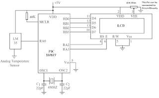
The circuit diagram of the thermometer:
 |
| Circuit Diagram of Digital Thermometer using PIC Microcontroller |
 |
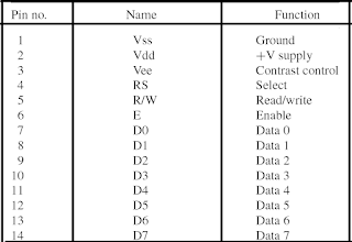
| LCD PIN CONNECTIONS and FUNCTIONS |
- LM016L: It is consist of 2 rows × 16 characters in each row, total 32 characters can be display at a time.
- LM017L: It is consist of 2 rows × 20 characters in each row, total 40 characters can be display at a time.
- LM018L: It is consist of 2 rows × 40 characters in each row, total 80 characters can be display at a time.
- LM044L: It is consist of 4 rows × 20 characters in each row, total 80 characters can be display at a time.
The
PICC language have built in libraries to handle LCDs based on controller HD44780
and the data/ text can be very easily displayed it using built in functions.
The following built in library functions are used to control the LCD with PIC
microcontroller using PICC Compiler:
- lcd init: To initialize the LCD at start of program, when controller is power ON, the code inside this function is executed to initiate the LCD to make it ready for accepting for commands to display user text on user define location of LCD etc.
- lcd clear: To clear the screen of whole LCD , all previously display text will b washed and the cursor will point to the home location means at the start of LCD.
- lcd goto: This function is used to bring the cursor at desired location/position
- lcd write: It is used to send a character to the LCD for display of a single character.
- lcd puts: It is used to send a text string to the LCD for display of test.
The
LCDs based on HD44780 type controller have 14 pins. The following figure shows
the pin numbers and their function. The Pin 3 of LCD is used to control the
contrast of the display, normally a variable resistor is used with this, but
for simplicity it can be directly tied to ground for full contrast. The RS pin of
LCD is used to send a control or a text depends on the logic on this pin. When
the read or write (R/W) pin of LCD is at logic level 0, a command or a text
message can be sent to the LCD. When R/W is at logic level 1, the LCD status
can be read. The LCD is enabled when the E pin of LCD is at logic level 0,
therefore it is also normally connected to ground for permanent enable
condition. Pins D0 to D7 of LCD are the data inputs pins. There are two modes
of interface 8 bit or 4 bit mode. The LCD in full 8-bit mode is connected to 8
lines of microcontroller, whereas, or in 4-bit half mode only the upper four
data pins are connected to four i/o lines of microcontroller. Usually the 4-bit
mode is preferred as it uses fewer pins of microcontroller. In order to use the
PICC, pre written library LCD functions, the LCD shall be connected in a predefine
hardware connection with microcontroller which are as follows,
Microcontroller Port
pin LCD pin
RB0 D4
RB1 D5
RB2 D6
RB3 D7
RA2 RS
RA3 E
Software of The Thermometer
//*******************************************************************
//
// DIGITAL THERMOMETER USING
LM35 AND PIC 16F877
//
============================
// Author: Dr. Rana
// Date: 17 August 2022
// File: DIGITAL-THERMOMETER.C
// The coding listing
in this program will read the raw-data Temperature form a LM35DZ analog
// sensor after one second
and then displays the measured raw-data Temperature on an Alphanumeric LCD.
// The microcontroller PIC
16f877 is configured to operate on a 4MHz crystal.
//
//*******************************************************************
#include <pic.h>
// PIC Library having all basic definition of PIC Microcontroller
#include
<delay.c> // The Delay Libray used to introduce some delay functions in
the code listing
#include <lcd.c>
// To control LCD, this built in Library or header file is included
#include
<stdio.h> // the compiler’s built in library to handle text strings efficiently
// Delay Function of
about one second
void wait a second()
{
unsigned int j;
for(j = 0; j < 4;
j++)DelayMs(250);
}
// Main Program start
here
main(void)
{
const float Volt2number
= 5000.0/1024.0; // declaration and unitization of variable
float milliVolt, raw-data,
raw-data-one, raw-data-high;
unsigned int raw-data-temp;
// declaration and unitization of variable
unsigned char disp[] =
"RAW-DATA = ";// declaration and unitization of variable
TRISA = 1; /* RA0 is
input, others output */
TRISB = 0; /* PORT B is
output */
ADCON1 = 0x8E; /*
RA0=analog, RA2,RA3=digital */
ADCON0 = 0x41; /*
Configure A/D clock and select channel 0 */
for(;;)// While One
function, it be executed as long as the MCU is power ON
{
ADCON0 = 0x45; /* Start
A/D conversion */
while(ADCON0 & 4)
!= 0); /* Wait for conversion */
raw-data-high = ADRESH;
/* Read upper 2 bits */
raw-data-one = ADRESL;
/* Read lower 8 bits */
raw-data = 256.0*raw-data-high
+ raw-data-one; /* Raw-data corresponds to Temperature in digital */
milliVolt = raw-data *Volt2number;
/* Raw-data corresponds to Temperature in milli-Volt */
raw-data-temp = milli-Volt
/ 10.0; /* Raw-data corresponds to Temperature in Centigrade. (10milliVolt/C)
*/
sprintf(disp+7,
"%d",raw-data-temp); /* Convert raw-data to Temperature to a string
*/
lcd puts(raw-data-temp);
/* Display raw-data Temperature on LCD */
wait a second(); /* delay
of one second */
lcd clear(); /* Clear
display */
}// end of while one
function
}// end of main
function and also end of code listing
Digital Thermometer Using Arduino & LM35 Temperature, temperature sensor using 8051 microcontroller pdf, Components Required: ; 1, Arduino UNO Board ; 2, LM35 Temperature Sensor ; 3, 16x2 LCD Display ; 4, Potentiometer 10K ; 5, Connecting Wires, temperature sensor using microcontroller, Building a digital thermometer using Lm35 and pic18f2580, What is analog temperature sensor? , How to Simplify the Interface between Microcontroller, The µC reads the output code of an analog-to-digital converter (ADC) driven by a thermistor-resistor voltage divider, analog-output temperature sensor, digital thermometer using lm35 and 8051 microcontroller, What is the construction of electronic thermometer?, Thermometer can be easily constructed using a PIC Microcontroller and LM35 Temperature Sensor. LM35 series is a low cost and precision Integrated Circuit, LM35 Temperature Sensor: Build Your Own Digital, digital thermometer project using arduino, What microcontroller is used in thermometer?, how to interface temperature sensor with microcontroller, digital thermometer using arduino and lm35 temperature sensor research paper, How to construct digital thermometer using LM35 and Arduino? ,Design and Implimentation of a Microcontroller Based , Digital Thermometer using a PIC Microcontroller and DS18B20, digital thermometer project without arduino, thermometer using 8051 microcontroller ppt ,digital thermometer project report pdf ,What is the construction and working of temperature sensor? ,The design is in four modules; power supply, temperature sensor, ... In this paper a digital thermometer was designed and constructed using AVR ,digital thermometer using 8051 microcontroller project report ,digital thermometer project report ,What is the construction of electronic thermometer?, Digital Thermometer using PIC Microcontroller and LM35, temperature sensor using pic16f877a microcontroller, How does a temperature sensor work in a microcontroller?, How does an analog temperature sensor work? ,UC using digital thermometer project report ppt, Microcntroller based thermometer using arduino project report, MCU based digital thermometer using arduino pdf ,arduino temperature sensor project pdf


No comments:
Post a Comment
Please ask if you have any question regarding the programming of MCU, or have any problem in development of your electronics project. microcontroller51.blogspot.com